The door lock assembly on the Whirlpool GHW9100LQ is both a safety device and a cycle prerequisite. The Central Control Unit (CCU) will not begin any cycle that involves drum movement unless it receives confirmation from the door lock switch that the door is securely latched and locked. This design is correct and intentional: a front-load washer at 1,000 RPM with an unlocked door is a serious safety hazard, and the interlock ensures this cannot occur. The consequence of this design, however, is that a door lock assembly failure, whether in the solenoid that mechanically locks the latch or in the switches that confirm the locked state, can prevent the washer from operating at all, or can leave the door locked at the end of a cycle with no apparent way to open it.
Understanding how the door lock assembly works electrically and mechanically, knowing how to test each of its internal components, and knowing what each test result indicates is essential for diagnosing the full range of door lock-related failures on this platform.
THE DOOR LOCK ASSEMBLY: COMPONENTS AND FUNCTION
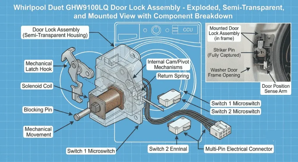
The GHW9100LQ’s door lock assembly (also called the door latch assembly or door interlock) is a single integrated unit mounted inside the front panel at the door opening’s right or left edge. It consists of:
The mechanical latch
A spring-loaded hook that captures the door striker pin when the door is closed. The latch is passive; it does not require electrical power to hold the door closed, only to lock it against manual opening.
The solenoid actuator
A DC solenoid coil that, when energized by the CCU, mechanically extends a blocking pin that prevents the latch from being retracted. This is what makes the door physically impossible to open during a cycle; the solenoid holds the blocking pin in the lock position.
Switch 1 – Door latch switch (door closed detection): A microswitch that closes when the door is fully shut, and the latch has captured the striker. This tells the CCU that the door is physically closed.
Switch 2 – Door lock switch (door locked detection): A microswitch that closes after the solenoid has extended the blocking pin and the door is in the fully locked state. This tells the CCU that the door is locked and the cycle can proceed.
Some GHW9100LQ door lock assemblies contain three switches, with the third switch providing a secondary lock confirmation or a thermal bimetallic element that prevents door opening immediately after a hot wash cycle (a thermal delay lock).
The CCU requires both Switch 1 and Switch 2 to confirm their expected states at each stage of the cycle. If either switch fails to confirm the expected state within the CCU’s timeout window, the cycle halts, and a fault code is generated.
DOOR LOCK PART NUMBER AND IDENTIFICATION
- Assembly part number: WP8182634 (current service replacement)
- Cross-reference numbers: 8182634, AP3866103, PS8260382
- Connector: 6-pin or 8-pin multi-pin connector (pin count varies between production runs; match the connector on removal)
FAULT CODES RELATED TO THE DOOR LOCK
F/dL (Door Lock fault): The CCU commanded the solenoid to lock the door but did not receive confirmation from Switch 2 within the timeout period (typically 60 seconds). Causes: solenoid failure, Switch 2 failure, harness fault, or CCU output relay failure.
F/dU (Door Unlock fault): The CCU commanded the solenoid to release, but the door did not register as unlocked within the timeout. Causes: solenoid is stuck in lock position, Switch 2 failure in the locked state, or mechanical obstruction of the blocking pin.
The door unlock fault (F/dU) produces the symptom described in the companion guide Why Whirlpool GHW9100LQ Door Stays Locked and Won’t Open at the End of a Cycle the door physically cannot be opened because the solenoid has not released the blocking pin.
SAFETY: EMERGENCY DOOR RELEASE
Before beginning any testing, note that the GHW9100LQ has an emergency door release mechanism a colored pull tab (typically orange or blue) accessible from inside the door boot area or from below the lower front panel. Pulling this tab mechanically releases the door lock solenoid’s blocking pin without electrical power, allowing the door to be opened even when the solenoid is energized or the machine has power.
This emergency release is used to manually open the door when testing with the machine powered. Always have the emergency release accessible when performing live electrical tests on the door lock assembly.
TEST 1: SOLENOID COIL RESISTANCE TEST
The solenoid coil can be tested for electrical continuity and correct resistance with a multimeter. A solenoid coil with open-circuit windings cannot generate the electromagnetic field needed to extend the blocking pin, resulting in an F/dL fault code (door won’t lock).
Procedure:
1. Unplug the washer. Disconnect the door lock connector from the machine harness.
2. Set the multimeter to resistance (ohm) measurement.
3. Identify the solenoid coil terminals on the door lock connector. The solenoid typically uses two of the connector’s pins (varies by production variant; refer to the wiring diagram for pin assignment).
4. Measure resistance between the solenoid terminals.
Expected reading: A functional solenoid coil on the GHW9100LQ door lock measures approximately 90–120 ohms at room temperature.
Open circuit (OL / infinite resistance): Solenoid coil is broken internally; assembly requires replacement.
Near-zero resistance (0–5 ohms): Solenoid coil has a short circuit; assembly requires replacement.
Resistance within range (90–120 ohms): Solenoid coil is electrically intact; the fault is elsewhere.
TEST 2: DOOR CLOSED SWITCH (SWITCH 1) CONTINUITY TEST
Switch 1 confirms door closure to the CCU. A failed Switch 1 causes the machine to behave as though the door is always open or always closed, depending on the failure mode.
Procedure:
1. Keep the washer unplugged and the door lock connector disconnected.
2. Identify the Switch 1 terminals on the connector (typically labeled COM and NO Common and Normally Open).
3. Test with a multimeter in continuity mode (audible continuity beeper if equipped).
4. With the door lock assembly’s latch in the open (unlatched) position, the switch should be open (no continuity between COM and NO).
5. Manually actuate the latch to the closed position (depress the latch catch as if a striker had entered): continuity should now be present between COM and NO.
If the switch does not change state correctly with mechanical actuation: Switch 1 has failed; assembly replacement required.
TEST 3: DOOR LOCKED SWITCH (SWITCH 2) CONTINUITY TEST
Switch 2 confirms the locked state; this is the switch that must close after the solenoid extends the blocking pin. It is the switch most commonly involved in F/dL fault codes.
Procedure:
1. Same initial setup as Test 2 (machine unplugged, connector disconnected).
2. Identify Switch 2 terminals on the connector.
3. With the assembly in the unlocked state: Switch 2 should be open.
4. Manually extend the solenoid blocking pin (this can be done by inserting a thin tool into the solenoid actuator port to simulate solenoid extension, or by using a 9–12V DC source to briefly energize the solenoid while testing with the machine unplugged and the connector isolated for the switch test).
5. In the locked state: Switch 2 should close (continuity between its terminals).
If Switch 2 does not close when the blocking pin is extended: Switch 2 has failed; assembly replacement is required.
DOOR LOCK ASSEMBLY REPLACEMENT PROCEDURE
If any of the above tests indicate a failed component within the assembly, the entire door lock assembly is replaced as a unit the individual solenoid, switches, and latch are not available as discrete service parts.
Step 1 – Remove the door boot gasket at the front panel edge (loosen the spring retaining ring to peel the gasket away from the front panel) to access the door lock assembly mounting.
Step 2 – Remove the 2–3 screws securing the door lock assembly to the front panel inner frame.
Step 3 – Disconnect the wiring harness connector from the old assembly.
Step 4 – Transfer the new assembly into position, reconnect the harness, and secure with the mounting screws.
Step 5 – Reinstall the door boot gasket.
Step 6 – Test cycle: run a short cycle and confirm the door locks (LED/display shows locked), the cycle completes, and the door unlocks normally at the end.