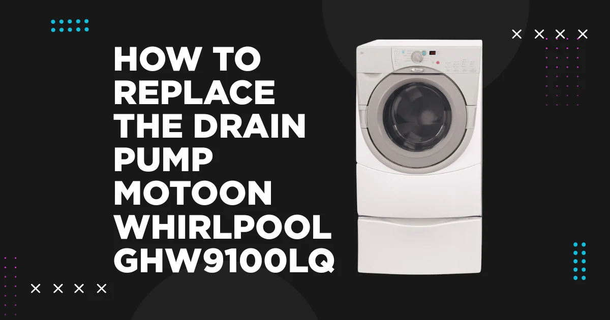
The drain pump motor on the Whirlpool GHW9100LQ is a continuously operated component; it runs every time the washer needs to remove water from the drum, which happens multiple times per cycle during the rinse and spin phases. Because it operates under load (pumping water against the head pressure of the drain hose), with direct contact with the water and debris that accumulate in the pump housing, the drain pump is one of the GHW9100LQ’s most mechanically stressed components and one of the most frequently replaced. Understanding why drain pumps fail, how to confirm the pump is the correct repair target, and how to execute the replacement correctly without secondary leaks or installation errors is the complete scope of this guide.
THE DRAIN PUMP ASSEMBLY: FUNCTION AND ARCHITECTURE
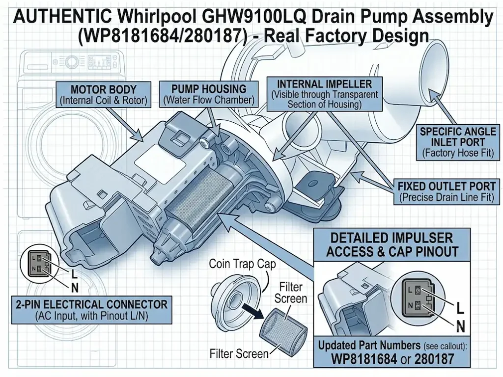
The GHW9100LQ drain pump is a centrifugal pump driven by a permanent magnet DC motor or a small synchronous AC motor (variant depends on production batch). The pump impeller is housed in a plastic pump body that connects to the tub drain outlet on one side and the household drain line on the other.
The pump is energized by the CCU (Central Control Unit) at defined points in each cycle:
- End of each wash phase (removing wash water)
- During rinse pauses (removing rinse water)
- During the spin ramp-up (pre-spin drain to reduce water load)
- During final spin (continuous drain of extracted water)
The coin trap (debris filter) is an integral part of the pump assembly on the GHW9100LQ, a small cylindrical filter trap accessible from the front lower panel that collects coins, buttons, lint, and small items before they reach the impeller. A blocked coin trap is one of the most common causes of drain problems on this machine and should always be checked before condemning the pump motor.
PART NUMBER AND SPECIFICATIONS
Primary OEM part number: WP8181684
Cross-reference numbers: 8181684, AP3866439, PS990806
Assembly type: Complete pump motor assembly (motor and pump body as a single unit)
Voltage: 120V AC
Typical current draw: 1.0-1.5A during normal pumping operation
Motor type: Synchronous AC pump motor (brushless, permanent magnet)
Impeller diameter: approximately 55- 65 mm
Compatible models: GHW9100LQ, GHW9100LW, and related first-generation Duet models
DIAGNOSING DRAIN PUMP FAILURE: CONFIRMING THE CORRECT REPAIR TARGET
Before ordering the pump, confirm it is the actual failed component and not a clog, a wiring fault, or a CCU output relay failure.
Fault Code F02 (Long Drain)
The F02 code is generated when the CCU commands the drain pump to run, but the water level sensor does not confirm a water level drop within a defined timeout (approximately 8 minutes). F02 does not exclusively indicate a failed pump motor; it indicates a drain system failure that could be the pump, a blocked coin trap, a kinked drain hose, or a drain hose positioned too low (creating a siphon that prevents effective draining). Full diagnosis of F02 is covered in the companion guide How to Fix Whirlpool GHW9100LQ Error Code F02 (Long Drain Fault).
Before condemning the pump motor
Step 1: Check and clean the coin trap. A coin trap packed with lint and debris can restrict flow sufficiently to trigger F02 without any pump motor fault.
Step 2: Check the drain hose for kinks, blockages, or incorrect positioning. The drain hose standpipe must be between 39 and 96 inches high; too low creates a siphon; too high creates excessive back-pressure.
Step 3: Listen during a drain cycle. A functional pump motor produces a consistent humming sound during drain operation. No sound = motor not energized (check CCU output) or motor burned out. Loud grinding or rattling = impeller obstruction or bearing failure. Humming but no water movement = impeller jammed or clogged.
Step 4: Test pump motor winding resistance. Disconnect the pump motor connector. Measure resistance across the two motor terminals. A functional motor measures approximately 10-15 ohms. Open circuit (OL) confirms motor failure.
TOOLS REQUIRED
- Phillips-head screwdriver (PH2)
- Flat-head screwdriver (medium)
- Slip-joint pliers or hose clamp pliers
- Large shallow pan or towels (water will drain from hoses during removal)
- Shop vacuum (to manage residual water in the tub)
- Multimeter (for motor resistance test if not already performed)
- Bucket
PRELIMINARY: DRAIN RESIDUAL WATER BEFORE DISASSEMBLY
If the machine has an F02 fault and contains standing water, drain it manually before beginning disassembly. Attempting to disconnect hoses with a drum full of water results in a flood. The complete procedure for manually draining the GHW9100LQ through the coin trap, including the correct method for a machine that cannot run, is covered in the companion guide How to Manually Drain Water from a Dead Whirlpool GHW9100LQ (Coin Trap Cleanout).
After draining: unplug the machine from the wall outlet. Never work on the pump or any electrical component with the machine plugged in.
STEP-BY-STEP DRAIN PUMP REPLACEMENT
Step 1 – Remove the lower front access panel
The lower front panel is retained by two or three screws at its base. Remove the screws, pull the bottom of the panel outward, then lift the panel to disengage its top clips from the frame. Set aside.
Step 2 – Locate the drain pump assembly
The drain pump is visible in the lower-front cavity of the machine, typically on the left or right side of the base frame. The large circular coin trap cap is the most visible feature; it faces forward for front-access service.
Step 3 – Clean the coin trap
Before removing the pump, unscrew the coin trap cap counterclockwise (it has a large plastic handle or wing tabs). Position a shallow pan beneath it to catch residual water. Remove the cap, extract the coin trap filter, and clean any accumulated debris. Inspect the impeller area for obstructions; items that passed the coin trap can jam the impeller.
Step 4 – Disconnect the electrical connector
Locate the 2-pin connector on the pump motor body. Squeeze the locking tab and pull the connector straight off. Verify the terminals are clean and undamaged; corroded pump motor connector terminals can mimic pump motor failure and should be noted if visible corrosion is present.
Step 5 – Loosen and remove the inlet hose clamp
The inlet hose (from the tub to the pump) is secured with a spring clamp or screw clamp at the pump’s inlet barb. Using pliers, compress the spring clamp and slide it back along the hose. Pull the hose off the inlet barb. Some residual water will drain; have the pan positioned.
Step 6 – Loosen and remove the outlet hose clamp
The outlet hose (from the pump to the household drain line) is secured similarly. Remove its clamp and pull the hose off the pump’s outlet barb.
Step 7 – Remove pump mounting screws and extract the pump
The drain pump is secured to the machine’s base frame by 2-3 screws. Remove these screws and lift the pump out of the cavity. The pump mounting orientation should be noted for correct reinstallation.
Step 8 – Install the replacement pump
Position the new WP8181684 assembly in the correct orientation (outlet barb toward the drain hose, inlet barb toward the tub drain hose). Start all mounting screws by hand before tightening any; this ensures the pump seats correctly without cross-threading.
Step 9 – Reconnect hoses
Slide both hoses onto their respective barbs and position the clamps directly behind the barb ridge, not further along the smooth hose body. Spring clamps must fully seat in the groove behind the barb for reliable sealing.
Step 10 – Reconnect the electrical connector
Align the 2-pin wiring harness connector with the terminals on the new pump motor body. Push the connector firmly onto the terminals until the locking tab audibly clicks into place. Ensure the connection is tight and secure to prevent electrical arcing or disconnection during the machine’s spin cycle.
Step 11 – Reinstall the coin trap filter and coin trap cap
Tighten the cap firmly by hand clockwise until snug. Do not use tools to tighten the cap; the plastic threads can crack.
Step 12 – Reinstall the lower front access panel
Hook the top clips of the access panel back onto the washing machine’s frame. Push the bottom of the panel flush against the base, align the screw holes, and reinsert the two or three mounting screws. Tighten them securely, but be careful not to overtighten and strip the plastic or metal threads.
POST-REPLACEMENT TESTING
Plug in the machine. Run a short cycle (Rinse & Spin is ideal; it fills briefly then drains). Observe:
- Active drain phases: confirm the pump is running (audible hum)
- No water pooling at the machine base (confirms all hose clamps are sealing)
- Cycle completes without F02 fault code
- Coin trap cap area is dry (confirms cap is fully tightened)