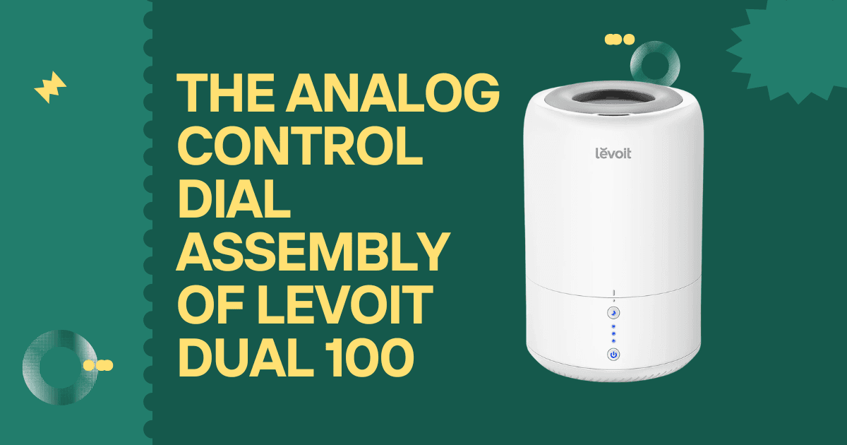
The analog control dial on the Levoit Dual 100 is the machine’s only user interface: a single rotary knob that controls the entire range of the humidifier’s mist output from minimum to maximum. Unlike the app-connected smart controls of Levoit’s higher-end models, the Dual 100 is deliberately simple: no display, no buttons, no connectivity. The rotary potentiometer is where all control intelligence lives. Understanding what a potentiometer is, how this specific one works within the Dual 100’s circuit, what its mechanical failure modes are, and how each failure mode manifests as an observable symptom is the technical foundation for diagnosing the full range of the Dual 100’s mist output and power-on problems that originate at the dial rather than in the transducer or fan.
WHAT A POTENTIOMETER IS: THE ELECTRICAL PRINCIPLE
A potentiometer is a three-terminal variable resistor. Its internal construction consists of a resistive element a carbon film, cermet, or conductive plastic track in the shape of an arc with a fixed terminal at each end of the arc (the two ends of the resistive element) and a sliding contact called the wiper that can be positioned anywhere along the arc’s length. The wiper is mechanically connected to the shaft that the user’s dial knob is attached to.
The electrical behavior this creates
- Between the two end terminals: a fixed resistance (the total resistance of the full arc; this value is constant regardless of shaft position)
- Between either end terminal and the wiper terminal: a variable resistance proportional to how far the wiper has traveled along the arc
In the Levoit Dual 100’s circuit, only two of the three potentiometer terminals are used in the conventional sense: one end terminal provides a reference voltage, the wiper terminal provides a variable output voltage that changes as the dial is rotated, and the other end terminal connects to ground. As the wiper moves from the grounded end to the supply end, the output voltage at the wiper terminal rises from near-zero to near-supply voltage, a continuously variable analog signal that represents the user’s selected mist intensity.
THE DUAL 100 POTENTIOMETER: SPECIFICATIONS
Potentiometer type: Rotary carbon-track (most common at this price tier)
Rotational range: approximately 270–300 degrees (from minimum to maximum, the shaft cannot complete a full 360-degree rotation, which is why the dial has a defined start and end stop)
Total resistance: approximately 10 kΩ to 50 kΩ (varies between production runs; the specific value is set at design to match the circuit’s input impedance)
Shaft diameter: approximately 6mm (standard for small appliance dial assemblies)
Mounting: PCB-mount with 3 solder pins (alternatively, wire-connected with flying leads to the PCB)
The potentiometer in the Dual 100 is a small component approximately 15-20 mm in diameter, mounted either directly to the main PCB or to a sub-board adjacent to the front housing where the dial knob protrudes. The dial knob is a separate press-fit or set-screw-secured plastic cap on the potentiometer shaft.
HOW THE WIPER VOLTAGE CONTROLS MIST OUTPUT
The wiper voltage from the potentiometer reaches the main circuit board’s oscillator section, specifically the control input of the transistor or MOSFET driver that sets the drive amplitude delivered to the transducer disc.
At minimum dial position (wiper near the grounded end): wiper voltage is near 0V → oscillator drive amplitude is minimal → transducer vibrates at low amplitude → minimal mist output (or no mist at the extreme minimum, depending on the circuit’s minimum threshold)
At maximum dial position (wiper at the supply voltage end): wiper voltage is near the supply voltage → oscillator drive amplitude is maximum → transducer vibrates at full amplitude → maximum mist output
The relationship between dial position and mist output is approximately linear in the Dual 100; a midpoint dial position produces roughly midpoint mist output. Some users notice the mist is barely visible at low dial settings; this is expected behavior from the low-amplitude transducer drive at minimum settings, not a fault.
The dial also incorporates the power on/off function on many production variants: turning the dial past the minimum stop clicks the built-in power switch, a mechanically integrated switching contact that disconnects the main power supply from the PCB. This means the dial is both the mist intensity control and the power switch simultaneously. A potentiometer with a failed integrated switch does not turn the unit on regardless of dial position.
POTENTIOMETER FAILURE MODES AND THEIR SYMPTOMS
Failure Mode 1 – Wiper track wear (intermittent or crackling output)
The wiper contact slides across the resistive track thousands of times over the product’s lifetime. The track gradually wears at the wiper contact point, creating a microscopic furrow that the wiper skips across with intermittent contact. The symptom is mist output that cuts in and out as the dial is adjusted through a specific range; the user experiences “dead zones” or crackle noise and mist jumping between levels as the dial crosses the worn track section.
This is the most common potentiometer failure mode. It is most noticeable at specific dial positions where the mist output is stable at maximum and minimum but erratic in the middle range (where wiper wear is concentrated, since that is the most frequently used range).
Failure Mode 2 – Wiper contact corrosion (high-resistance output):
In humid environments, which the Dual 100 inherently creates around itself, the wiper contact and the carbon track can develop oxidation or hygroscopic contamination that increases the contact resistance. The symptom is consistently lower mist output than the dial position indicates, and a “floating” voltage at the wiper output (the circuit board sees an incorrectly low or unstable control signal).
Failure Mode 3 – Integrated power switch failure (unit will not turn on)
As described above, the dial’s built-in switch contacts can wear, corrode, or develop an open circuit. The unit does not turn on when the dial is turned past the minimum stop. The indicator light does not illuminate. The full power-on diagnosis, including how to check the dial switch versus other no-power causes, is covered in the companion guide Why Your Levoit Dual 100 Won’t Turn On (Checking the Fuse and Analog Dial Connectivity).
Failure Mode 4 – Shaft mechanical failure:
The plastic potentiometer shaft or the interface between the shaft and the dial knob can fail; the shaft becomes loose in its bearing (producing a wobbly dial feel), or the connection between shaft and knob strips (knob spins freely without turning the shaft). This is a mechanical failure that prevents any mist level adjustment regardless of the potentiometer’s electrical condition.
DIAGNOSING POTENTIOMETER VERSUS CIRCUIT BOARD FAULTS
When mist output is erratic, or the unit will not turn on, the potentiometer and the main circuit board are both candidates. Distinguishing between them requires one of two approaches:
Approach 1 – Resistance test:
Unplug the unit. Access the potentiometer terminals (requires housing disassembly as described in the fan motor replacement guide). Measure the total resistance between the two end terminals; it should read the rated value (10–50 kΩ). Then slowly rotate the shaft while measuring between one end terminal and the wiper terminal; the resistance should increase or decrease smoothly and continuously with no sudden jumps or open-circuit interruptions. Any jumps or dead zones confirm wiper track wear.
Approach 2 – Voltage substitution test
With the unit assembled and running, apply a fixed voltage to the circuit board’s control input (the wiper input) using a voltage divider constructed from fixed resistors, bypassing the potentiometer. If the transducer produces stable mist output with the fixed voltage input, the potentiometer has failed. If the output is still erratic with a fixed input, the circuit board’s control section has failed.
REPLACING THE POTENTIOMETER
The Levoit Dual 100 potentiometer is a standard rotary potentiometer available from electronics components suppliers. When ordering a replacement:
- Match total resistance value (measure the original before removal or note the part number printed on the component body)
- Match shaft diameter (6mm standard)
- Match mounting configuration (PCB-mount vs. wire-lead configuration)
- Match the switch type if the integrated switch is present (single-pole single-throw switch integrated into the potentiometer body)
Replacement requires PCB-level soldering (desoldering the three or five pins of the original potentiometer and soldering the replacement). This is a standard through-hole soldering task accessible to anyone with basic electronics soldering skills and a 25-30W iron