The motor and capacitor assembly in the Levoit Core 200S is the mechanical engine of the entire air purification system. Every cubic foot of air that passes through the three-stage filtration system does so because this motor is turning the centrifugal impeller at the correct speed and torque against the resistance of the filter stack. When the motor degrades, runs slower than specification, or fails entirely, no amount of filter maintenance restores performance; the limiting factor has moved from the filtration media to the mechanical drive system itself.
Understanding the Core 200S motor’s specifications, its type, operating parameters, winding characteristics, capacitor role, and failure modes is the technical foundation for accurate diagnosis of airflow problems, noise complaints, and complete motor failure events. It is also the prerequisite knowledge for sourcing a compatible replacement motor when repair becomes necessary.
THE MOTOR ARCHITECTURE: BRUSHLESS DC IN A 120V AC APPLIANCE
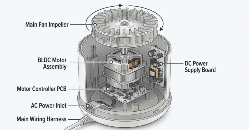
The Levoit Core 200S uses a Brushless DC (BLDC) motor despite operating from a standard 120V AC wall outlet. This is not a contradiction; it reflects how modern compact appliance motors are designed.
The machine’s internal power supply converts 120V AC mains power into a regulated DC voltage (typically 12V or 24V DC, depending on the specific motor variant) that drives the BLDC motor. The motor controller an integrated circuit on the main PCB, manages commutation: the precise timing of current switching through the motor’s stator windings that creates the rotating magnetic field driving the permanent-magnet rotor.
Why BLDC instead of a traditional AC induction motor:
A conventional single-phase AC induction motor at this scale would require a run capacitor to create the phase shift needed for starting torque, which is where the “AC capacitor” reference in the Core 200S’s technical context originates. However, the Core 200S’s internal architecture converts to DC before the motor, making the primary motor a BLDC type. The capacitor present in the power supply circuit serves a different function than a traditional AC motor run capacitor; it is a filter/decoupling capacitor in the DC bus, not a phase-shift capacitor.
This distinction matters for repair technicians:
If the Core 200S motor is not spinning or runs inconsistently, the diagnosis pathway for a BLDC motor system differs fundamentally from that of a capacitor-start AC induction motor. The capacitor in a BLDC power supply circuit failing produces different symptoms (ripple voltage, instability, voltage sag under load) compared to a traditional AC motor capacitor failure (failure to start, humming without rotation).
MOTOR SPECIFICATIONS
The following specifications apply to the standard Core 200S motor as found in the North American (120V/60Hz) production variant. Minor variations may exist across production runs and regional variants.
- Motor type: Brushless DC (BLDC), inner-rotor configuration
- Stator configuration: 3-phase, distributed winding
- Rotor: Permanent magnet (ferrite or rare-earth, depending on production variant)
- Motor shaft diameter: approximately 5 mm
- Motor outer diameter: approximately 55–65 mm
- Motor height (body only, excluding shaft): approximately 30–40 mm
- Operating voltage (motor terminals): 12V DC or 24V DC (determined by internal power supply; confirm on specific unit)
- No-load current draw: approximately 0.15–0.25A (at operating voltage)
- Full-load current draw: approximately 0.5–0.8A (at high-speed setting, against filter resistance)
Fan speed range:
- Sleep mode: approximately 600–800 RPM
- Low speed: approximately 1000–1200 RPM
- Medium speed: approximately 1500–1800 RPM
- High speed: approximately 2000–2400 RPM
These RPM values are approximate and vary between production runs. The motor controller manages speed by varying the PWM (Pulse Width Modulation) duty cycle of the drive signal higher duty cycle = higher effective voltage to the motor = higher RPM. This is why fan speed is continuously variable in Auto mode despite appearing as discrete settings on the control panel.
Winding resistance (phase-to-phase, at room temperature):
Varies by specific winding configuration, typically 8–20 ohms between any two of the three-phase terminals. Measuring significantly higher resistance (or open circuit) on any phase pair indicates a failed winding. Measuring near-zero resistance (short circuit) between phase terminals indicates a winding short.
THE CAPACITOR IN THE CORE 200S POWER CIRCUIT
As established above, the capacitor(s) in the Core 200S are DC bus filter capacitors, not AC motor run capacitors. Their function is to:
1. Filter rectified AC voltage into smooth DC for the motor drive circuit
2. Provide instantaneous current to the motor controller during commutation events (the brief current spikes when motor windings are switched)
3. Decouple the motor drive circuit from the mains power supply, preventing motor switching noise from feeding back into the mains
Capacitor specifications (DC bus filter capacitor):
Capacitance: typically 100–470 µF (microfarads), depending on the power supply design
Voltage rating: typically 35V or 50V DC (must be rated above the DC bus voltage with margin)
Type: Electrolytic aluminum capacitor
Physical form: cylindrical, approximately 8–12 mm diameter × 15–25 mm height
Capacitor failure in the Core 200S power supply:
Electrolytic capacitors have a finite service life measured in hours at rated temperature. The capacitor’s ESR (Equivalent Series Resistance) increases with age, and capacitance decreases. In the Core 200S power supply, a failing electrolytic capacitor manifests as:
- Motor stuttering or inconsistent speed (insufficient instantaneous current delivery)
- High-frequency whine from the power supply under load (switching frequency harmonics no longer filtered)
- Motor running at reduced speed despite correct control signals (voltage sag under load due to high ESR)
- In severe failure: swollen or leaking capacitor body visible on the PCB (the most definitive visual indicator)
A swollen or leaking electrolytic capacitor is an unambiguous replacement indicator. Capacitor replacement is a straightforward soldering task for technicians with basic electronics skills. The capacitor is a through-hole component on the power supply PCB, desoldered and replaced with a component of identical capacitance, voltage rating, and physical dimensions.
MOTOR CONTROLLER IC: ROLE AND FAILURE MODES
The motor controller IC on the main PCB manages all aspects of BLDC motor operation: commutation timing based on Hall sensor feedback (or sensorless back-EMF detection), PWM speed control, overcurrent protection, and thermal shutdown. In the Core 200S, this IC is typically a dedicated motor driver chip (common examples include chips from the DRV8xxx family from Texas Instruments or equivalent Chinese domestic equivalents).
Motor controller failure modes relevant to Core 200S symptoms:
- Motor does not start, but power supply is functional: Hall sensor signal missing or motor driver IC not receiving enable signal from the main MCU
- Motor runs erratically or only at one speed: PWM signal path fault between the main MCU and motor driver
- Motor shuts down after a few minutes of operation: thermal shutdown in motor driver IC, caused by insufficient PCB ventilation or a failing motor drawing excessive current
- Burning smell from the motor area without visible motor damage: motor driver IC failure, often preceded by a brief overcurrent event
The motor controller IC is a surface-mount component, and its replacement requires SMD soldering capability. For owners without this capability, the practical repair path is main PCB replacement rather than IC-level component repair.
MOTOR LOAD: HOW FILTER CONDITION AFFECTS MOTOR STRESS
A critical relationship exists between filter loading state and motor operating conditions. The centrifugal impeller moves air against the total pressure drop across the filter stack (pre-filter + HEPA + carbon layers). As the filter loads with captured particles over its service life, the pressure drop increases. The motor controller maintains the commanded speed by increasing current to the motor windings, which increases both power consumption and motor/driver temperatures.
A severely clogged filter (particularly one with an unwashed pre-filter) can increase motor current draw by 20–40% compared to operation with a clean filter. Over extended periods, this elevated thermal stress accelerates both motor winding insulation degradation and electrolytic capacitor aging, the two failure modes most commonly seen in well-used Core 200S units.
The practical maintenance implication: regular pre-filter washing is not only a filtration performance action, but it is also a motor protection action. Owners who maintain clean pre-filters reduce motor thermal stress and extend motor service life. The pre-filter maintenance procedure is detailed in the companion guide How to Clean the Washable Nylon Pre-Filter on Levoit Core 200S.
IDENTIFYING THE MOTOR ASSEMBLY FOR REPLACEMENT SOURCING
The Core 200S motor assembly is not a named/numbered component in Levoit’s public parts documentation. Sourcing a replacement requires either:
1. Contacting Levoit support directly with the unit’s serial number to request the motor assembly part number for the specific production run
2. Physical measurement of the installed motor (diameter, height, shaft diameter, connector type) to source a compatible BLDC motor from an electronics components supplier
3. Purchasing a complete replacement unit and harvesting the motor assembly (cost-effective only if the rest of the unit is functional and the donor unit is available at low cost)
When measuring the installed motor for replacement sourcing, document: outer diameter, body height, shaft diameter, shaft length, number of wires in the motor harness connector (3-wire = BLDC without Hall sensors; 5-wire or 6-wire = BLDC with Hall sensors), connector type and pitch, and the rotation direction (determined by impeller blade orientation).
For a comprehensive overview of the Core 200S’s complete electrical specifications, including rated wattage, voltage, and current at each speed setting, see the companion reference Levoit Core 200S Smart Air Purifier: Full Technical Specifications & Dimensions.
MOTOR AND NOISE: MECHANICAL SIGNATURES
A healthy Core 200S motor produces a consistent, smooth tonal hum at each speed setting with no mechanical vibration components above the normal impeller rotation frequency. Deviations from this baseline indicate specific mechanical conditions:
High-pitched whine above normal motor tone: bearing wear in early stages; the ball or sleeve bearing in the motor is beginning to develop surface irregularities
Irregular pulsing in the motor sound: commutation irregularity, Hall sensor degradation, or motor controller PWM instability
Grinding or scraping sound: contact between the impeller and the motor housing or fan shroud; impeller has shifted on the shaft, or housing has warped
Intermittent speed changes without input: motor driver thermal throttling under elevated ambient temperature or blocked ventilation path
Diagnosing and repairing noise issues, including impeller access, shaft inspection, and bearing assessment, is covered in the companion guide How to Fix a Rattling or Grinding Noise in Levoit Core 200S (Fan Motor Repair).