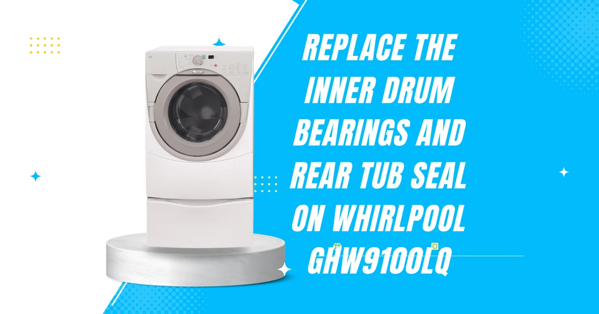
The inner drum bearings on the Whirlpool GHW9100LQ are the most mechanically demanding components to replace in the entire machine, and they are among the most consequential. These bearings support the drum shaft through millions of rotations over the machine’s service life, under loads that include the weight of wet laundry, the inertial forces of spin acceleration and deceleration, and the dynamic imbalance forces from uneven loads. When they fail, the failure is progressive and unmistakable: a steadily worsening roaring or grinding noise during spin that eventually becomes a constant presence during all drum motion. Ignoring failing drum bearings does not slow their deterioration it accelerates it, as the increasing shaft runout from worn bearings damages the rear tub seal, accelerates drive belt wear, and eventually damages the drum shaft itself.
This guide covers the complete bearing and seal replacement procedure. It is the most involved repair documented in this series it requires complete machine disassembly down to the outer tub assembly, and it should be approached with adequate preparation time and tooling.
UNDERSTANDING THE BEARING AND SEAL SYSTEM
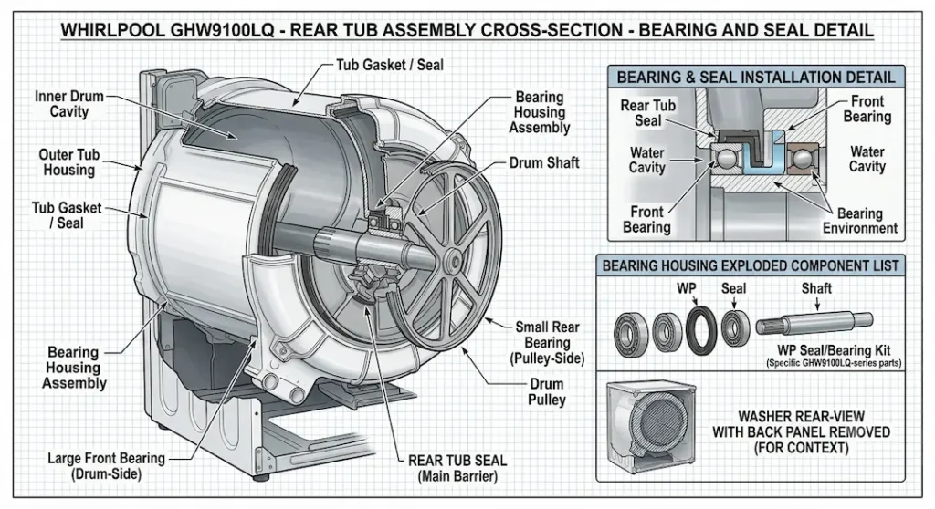
The GHW9100LQ drum shaft passes through the rear wall of the outer plastic tub via two bearings: a larger front bearing (supporting the primary radial load) and a smaller rear bearing (providing secondary support). Between the rear tub wall and the drum shaft, the rear tub seal prevents water from leaking out of the tub along the shaft.
The system operates as an integrated unit: the bearings are pressed into the rear tub housing with precise interference fits, and the seal is pressed into the rear tub wall adjacent to the bearings. When bearings wear, increased shaft runout causes the seal’s sealing lip to be subjected to eccentric motion it is not designed for, accelerating seal wear and leading to water leakage at the rear of the machine.
Bearing failure follows water seal failure in many cases (water contamination of a dry-lubricated bearing accelerates its destruction), which is why both bearings and the rear tub seal are always replaced as a set, not as individual components.
PART NUMBERS
Bearing kit: typically sold as a set containing both drum shaft bearings and the rear tub seal
Bearing kit part numbers: W10435302 (commonly cited), W10253866 (alternative), or aftermarket bearing/seal kits specifically listed as compatible with GHW9100LQ
Bearings are standard industrial bearings (61908-2RS or similar, depending on production batch). Confirm dimensions by measuring the removed bearings (inner diameter, outer diameter, width) before ordering if the kit part number is uncertain.
Rear tub seal part number: W10253864 (if purchasing separately)
DIAGNOSING BEARING FAILURE
Symptoms of failing drum bearings follow a characteristic progression:
Stage 1 – Intermittent rumbling during high-speed spin
A low-frequency rumbling or roaring sound, particularly during and just after the spin ramp-up phase. The sound may not be present during low-speed tumble.
Stage 2 – Constant grinding during all drum motion
As bearings wear further, the sound is present even at tumble speeds. The pitch and volume increase with drum speed.
Stage 3 – Metallic scraping or banging
Severely worn bearings produce metal-on-metal contact and may produce banging sounds as the drum shaft runs eccentrically.
Associated symptoms at Stage 2–3
- Water leaking from the rear of the machine (tub seal failure from shaft runout)
- Drive belt wearing or failing prematurely (increased shaft runout loads the belt unevenly)
- The machine failing to balance during spin cycles despite normal loads
The companion guide How to Fix Loud Roaring Banging Noises During Spin Cycle on Whirlpool GHW9100LQ covers the full differential diagnosis of spin noises, including how to confirm bearings vs. other noise sources such as foreign objects in the drum or worn shock absorbers.
TOOLS REQUIRED
- Complete set of Phillips and flat-head screwdrivers
- Nut drivers (1/4-inch and 5/16-inch)
- Torx screwdriver (T20 and T25)
- Slip-joint pliers and needle-nose pliers
- Bearing puller or slide hammer (for extracting old bearings from housing)
- Bearing driver set (or hardwood dowels and mallet) for pressing new bearings
- Snap ring pliers (if snap rings retain bearings)
- Rubber mallet
- Work surface: a large, clear table; disassembly produces many components that must be organized
DISASSEMBLY SEQUENCE TO ACCESS BEARINGS
Reaching the drum bearings requires nearly complete machine disassembly. The sequence below is the correct order for the GHW9100LQ; steps performed out of sequence typically result in inaccessible fasteners and wasted labor.
Step 1 – Drain the machine completely and unplug
Before beginning any disassembly, safety is the top priority. Unplug the washing machine from the wall outlet to eliminate any electrical hazard. Shut off the hot and cold water supply valves completely. Disconnect the water inlet hoses from the back of the machine, and place the drain hose into a low bucket or shallow pan to drain any residual water trapped inside the pump and hoses.
Step 2 – Remove the top panel
Locate the two or three hex-head or Torx screws securing the top panel at the upper rear edge of the machine. Remove these screws using the appropriate driver. Once the screws are out, slide the top panel back about an inch, then lift it straight up and off the cabinet frame. Set it aside in a safe place.
Step 3 – Remove the control console
With the top panel removed, locate the mounting screws holding the control console assembly along the top channel or inside the detergent dispenser drawer cavity. Carefully remove these screws, then slide or lift the console forward to disengage its plastic locking tabs. Before fully removing it, take a clear digital photograph of all the wire harness connections on the main control board for reference. Disconnect the wire harnesses and set the console aside.
Step 4 – Remove the front panel
Remove the door boot seal spring retaining ring (spring-wire ring around the door opening perimeter release with a flat screwdriver. Peel the door boot seal away from the front panel lip. Remove the front panel screws (typically at the top corners and lower edge) and lift the front panel away.
Step 5 – Remove the door boot seal from the tub
It remains attached to the tub’s front flange by a clamp. Loosen this clamp and remove the seal from the tub.
Step 6 – Remove the rear panel
Move to the back of the washing machine and locate the multiple screws around the outer perimeter of the rear metal panel. Remove all the screws using a nut driver. Carefully lift the heavy sheet metal panel away from the cabinet hooks to expose the drive motor, large drum pulley, and drive belt.
Step 7 – Disconnect all tub-attached hoses and wiring
- Tub drain hose
- Pressure switch hose
- Water inlet hoses (at the dispenser and tub inlet)
- Heater element wiring (if equipped)
- Thermistor connector
Step 8 – Remove the drive belt
Remove the belt from the drum pulley and motor pulley as described in the Drive Belt Replacement Guide.
Step 9 -Remove the counterweights
Typically, two concrete weights are bolted to the front and rear of the outer tub; these are heavy, 15-25 lbs each. Have an assistant hold each as the bolts are removed.
Step 10 – Disconnect the suspension shock absorbers and springs
See companion guide for the correct disconnection sequence: How to Install New Shock Absorbers. Support the tub assembly before disconnecting the suspension to prevent it from dropping.
Step 11 – Remove the outer
tub assembly from the machine cabinet, lift up and out through the front opening. The tub is heavy, 40-60 lbs when empty; have an assistant.
Step 12 – Separate the tub halves
The front and rear outer tub sections are bolted together; remove the perimeter bolts, typically 10-14 bolts, and separate the two halves to access the rear tub bearing housing.
BEARING AND SEAL REMOVAL AND INSTALLATION
Once the tub assembly is separated, you can proceed to service the core mechanical components. This section outlines the precise method for removing the worn bearings and seals, and pressing in the new replacements securely.
Step 1 – Remove the drum pulley from the shaft
The drum pulley is held by a single large bolt at the shaft end. Turn it counterclockwise to loosen while holding the drum firmly to prevent rotation. Once the bolt is out, slide the pulley off the splined shaft.
Step 2 – Extract the old bearings from the rear tub housing
Using a bearing puller, carefully extract the old bearings from the rear tub housing. The bearings are pressed in with an interference fit, meaning they require controlled, even force to extract without damaging or cracking the plastic housing bore.
Step 3 – Extract the old rear tub seal
Pry the old rear tub seal out from the inner tub side using a flat tool or pry bar. Be extremely careful not to scratch the housing wall. Once removed, clean the seal bore thoroughly to remove any rust, dirt, or old grease.
Step 4 – Press in the new rear tub seal
Apply a small amount of high-quality bearing grease to the new seal lip before installation. Use a bearing driver or a wooden block of matching diameter to press the seal in squarely. A crooked installation will cause immediate seal failure and water leaks.
Step 5 – Press in the new bearings
Install the larger front bearing first, then the smaller rear bearing. Press each bearing squarely into its bore by applying force only to the outer race (never press on the inner race, as this will damage the internal ball bearings). The bearing is correctly seated when it sits flush with or slightly below the housing bore face.
REASSEMBLY
Reassembly is the reverse of disassembly. Critical points:
- Apply fresh tub sealant (RTV silicone or equivalent) to the tub-half mating surfaces before joining the tub halves. Insufficient sealant causes tub leaks.
- Torque the tub-half bolts to specification (approximately 8-10 ft-lbs) in a crossing pattern to ensure even sealant compression.
- Replace the door boot seal simultaneously with the bearing replacement; accessing the boot seal during bearing replacement requires no additional disassembly, and a worn boot seal found during disassembly should be replaced proactively. The full boot seal procedure is in the companion guide Replacing the Rubber Door Boot Bellows Gasket on Whirlpool GHW9100LQ.