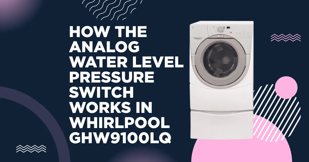
The water level pressure switch in the Whirlpool GHW9100LQ is the sensor that tells the Central Control Unit (CCU) how much water is in the wash tub at any given moment. Every fill and drain phase of every cycle depends on the CCU receiving accurate water level information from this switch; without it, the machine cannot know when to stop filling, cannot confirm that draining is progressing, and cannot safely initiate high-speed spin (spinning a full drum of water risks dangerous imbalance and overflow). When this switch fails, or its pressure circuit is compromised, the CCU makes incorrect decisions about fill and drain operations, generating FH or F20 fault codes and producing erratic behavior that is often misdiagnosed as an inlet valve or drain pump failure.
Understanding precisely how the GHW9100LQ’s water level sensing system works, including the pressure physics, the hose circuit from tub to switch, and the analog signal the switch produces, is the only way to diagnose it correctly rather than replacing functional components.
HOW THE PRESSURE SWITCH SYSTEM WORKS: THE PHYSICS
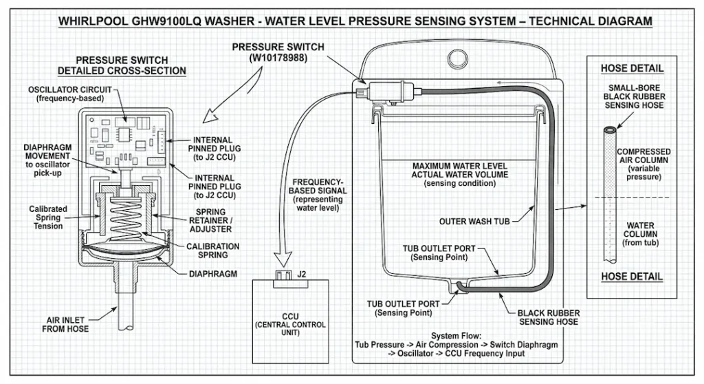
The GHW9100LQ does not measure water level with a float sensor or an ultrasonic sensor; it uses the physical principle of pneumatic pressure to translate water height in the drum into an electrical signal.
A small-diameter plastic hose runs from a port at the lowest point of the outer tub to the pressure switch mounted on the machine’s chassis. This hose creates a sealed air pocket between the tub port and the pressure switch diaphragm. As water fills the tub, the rising water level compresses the air in this sealed hose circuit; air pressure in the hose increases proportionally with water height. The pressure switch diaphragm flexes in response to this air pressure, and the flexion changes the electrical output of the switch.
This is a closed, air-filled circuit; no water should ever reach the pressure switch itself. If water does reach the switch body (typically from a hose that has cracked or from a siphon effect), the switch fails because its diaphragm is designed for air, not water contact.
The “analog” descriptor in the context of the GHW9100LQ’s pressure switch refers to the fact that the switch output is frequency-modulated rather than simple on/off: the switch contains a small oscillator whose output frequency changes continuously with diaphragm pressure. The CCU reads this frequency signal and maps it to a water level value, allowing precise water level monitoring rather than just “full/empty” binary detection.
PRESSURE SWITCH IDENTIFICATION AND PART NUMBER
Part number: WP8181715 (primary OEM service replacement)
Cross-reference numbers: 8181715, AP3866567, PS990448
Physical description: Small cylindrical or rectangular plastic body, approximately 35-45 mm diameter, mounted in the upper cabinet area accessible after removing the top panel. One pneumatic hose connection (for the air pressure line) and one multi-pin electrical connector (typically 3 or 4 pins for the frequency-modulated output and power supply).
THE PRESSURE HOSE CIRCUIT: THE MOST COMMON FAILURE POINT
The small-bore hose connecting the tub port to the pressure switch is the most failure-prone element of this system, not the switch itself. Hose failures include:
Cracks or splits in the hose body
The hose is a thin-wall plastic or rubber tube that becomes brittle with age, particularly in areas that are repeatedly flexed during the drum movement or repeatedly exposed to temperature cycling from hot wash cycles. A cracked hose creates an air leak that prevents pressure buildup; the CCU sees near-zero pressure (empty drum signal) regardless of actual water level.
Hose disconnection
The hose can work loose from either connection point (tub port or switch body) over time. A disconnected hose produces the same symptom as a cracked hose.
Water in the hose
If a siphon effect or a hose kink traps water in the hose, the air column is shortened. This causes the switch to read a higher pressure (higher water level) than actually exists; the CCU may cut off fill prematurely, resulting in underwashing, or may generate FH codes because the apparent water level doesn’t match the expected fill trajectory.
Hose Clog
Mineral deposits or detergent residue can partially occlude the hose bore, slowing the pressure equalization rate and causing the CCU to receive a delayed pressure signal.
Inspection procedure for the hose
Trace the hose from the tub port to the pressure switch. Inspect its full length for:
- Visible cracks (flex the hose gently; hairline cracks may open under flexion but not be visible when the hose is straight)
- Secure connections at both ends (no ability to pull either end off without releasing the retaining clip)
- No sharp kinks or tight bends that could restrict airflow
- No moisture inside the hose (disconnect one end and use a flashlight to look for water in the tube)
FAULT CODES GENERATED BY PRESSURE SWITCH FAULTS
FH (also appearing as F9 E1 or F/H on the display)
The CCU commanded the inlet valves to fill, but the pressure switch frequency did not change as expected within the fill timeout. The CCU interprets this as no water entering the drum.
Pressure switch as cause of FH
If the hose is cracked or disconnected, the pressure switch reads zero pressure at all times. As the drum fills with water, the CCU monitors for a pressure increase when no pressure signal change is received; the FH code triggers even though the drum is actually filling correctly.
This is the critical diagnostic distinction
With a hose fault, the drum may actually have water in it while the CCU is generating FH. The technician sees FH and suspects the inlet valve, replaces it, and finds FH persists because the inlet valve was always functional. The pressure hose should be the second thing checked after confirming supply water is available.
F20 (slow fill)
Similar to FH but specifically triggered when fill takes longer than expected rather than producing no pressure response at all. Can indicate a partially cracked hose that transmits some pressure but with attenuation.
TESTING THE PRESSURE SWITCH: PROCEDURES
Test 1 – Hose integrity air pressure test:
Disconnect the pressure hose at the switch body. Gently blow into the hose end while holding your finger lightly over the tub end. If you can blow air through without resistance (continuous airflow), the air circuit is intact and connected to the tub. If the air escapes at a crack or disconnection point along the hose length before reaching the tub, the fault location is identified.
Test 2 – Functional bench test of the switch:
With the switch disconnected from the machine and connected to a multimeter in resistance or frequency mode at its output terminals, gently apply air pressure to the pneumatic port (blow gently through a small tube inserted into the port). A functional switch changes its output signal in response to applied pressure. No change in output with applied pressure indicates switch diaphragm failure or oscillator circuit failure.
Test 3 – CCU frequency reading in diagnostic mode
The GHW9100LQ’s diagnostic test mode can display the current pressure switch frequency reading. This allows the pressure switch signal to be verified under actual tub water level conditions without component removal. At an empty tub (no water), the frequency should read the baseline empty value; after adding water, the reading should change proportionally. A reading that doesn’t change during fill confirms the air circuit fault. The diagnostic mode access procedure is in the companion guide How to Enter Diagnostic Test Mode on a Whirlpool Duet GHW9100LQ Washer.
REPLACING THE PRESSURE SWITCH
Switch replacement is straightforward:
1. Remove the top panel (2-3 screws at the rear, slide backward, lift).
2. Locate the switch in the upper chassis, typically mounted on the left or right side wall near the rear.
3. Disconnect the electrical connector.
4. Disconnect the pressure hose (pull the barbed connection straight off the switch port).
5. Remove the 1-2 mounting screws and remove the switch.
6. Install the replacement switch in reverse order.
When replacing the switch, replace the pressure hose simultaneously if it shows any aging, cracking, or discoloration; the hose is inexpensive, and its condition directly affects switch function. A new switch connected to a compromised hose will produce the same fault as a failed switch.
PRESSURE SWITCH IN THE CONTEXT OF SPIN SAFETY
The pressure switch also has a safety function in the spin cycle: the CCU will not allow the motor to accelerate to high spin speed (above approximately 300 RPM) until the pressure switch confirms that the water level has dropped below a defined threshold. This prevents high-speed spinning with a full or partially full drum, which would cause dangerous imbalance, excessive vibration, and potential water overflow.
If the pressure switch is stuck reading “full” (as can happen with water trapped in the hose), the machine may refuse to complete the spin cycle, appearing to spin briefly then stopping and restarting without ever reaching high speed. This symptom is easily confused with a motor, MCU, or imbalance issue.