The suspension system on the Whirlpool GHW9100LQ is the mechanical interface between the outer tub assembly, which holds up to 40 gallons of water and a full load of wet laundry during operation, and the machine’s outer cabinet. It must simultaneously allow the tub to move freely in response to the dynamic imbalance forces that occur during spin acceleration, while damping and controlling that movement so the tub does not impact the cabinet, and while preventing the vibration from transmitting to the floor. When the suspension system wears out, the result is a machine that shakes violently during spin cycles, walks across the floor, produces loud banging from tub-to-cabinet contact, and frequently fails to complete the spin cycle due to out-of-balance faults triggered by the excessive drum movement.
The GHW9100LQ’s suspension consists of two systems that work together: shock absorbers (dampers) that control the rate of tub movement, and suspension springs that define the natural resonant frequency of the tub-spring system. Both degrade independently, and replacing only one while leaving the other worn often produces an improvement but not a full restoration. This guide covers both replacements.
SUSPENSION SYSTEM ARCHITECTURE
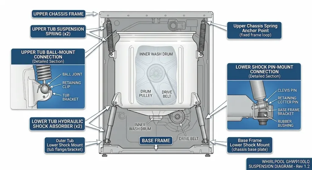
The GHW9100LQ uses a four-point suspension system:
Two shock absorbers
Positioned at the left and right base of the outer tub, connected between the tub’s lower mounting points and the machine’s base frame. These hydraulic or friction dampers resist the tub’s rapid vertical and lateral movement, converting kinetic energy to heat and preventing the tub from freely oscillating after each vibration impulse.
Two or four suspension springs
Positioned at the upper corners or sides of the outer tub, connected between the tub’s upper mounting points and the machine’s top frame or side panels. These tension springs provide the restoring force that returns the tub to its centered position after displacement and set the system’s resonant frequency.
The interaction between spring stiffness and shock damping coefficient determines the tub’s dynamic behavior during spin. Correctly matched suspension components allow the spin to ramp through the system’s resonant frequency quickly (the brief vibration maximum at resonance) and settle to a smooth, damped motion at operating speed.
PART NUMBERS
Shock absorbers
OEM part number: WP8182703 (each; the GHW9100LQ uses 2 identical shock absorbers)
Cross-reference: 8182703, AP3866835, PS991611
Suspension springs
OEM part number: WP8182703 if springs are integrated with suspension rods, or separately identified spring part numbers depending on production variant.
Common spring part numbers: W10780048 or W10198291 (verify against the specific machine using the full model number; spring configurations varied between production runs)
DIAGNOSING SUSPENSION FAILURE
Shock absorber failure symptoms
Worn shock absorbers lose their damping force, the damper fluid has leaked, or the internal friction mechanism has worn smooth. The tub is no longer controlled in its movement.
- Excessive vibration during any spin speed
- Machine walking forward or sideways during spin
- Loud banging from tub contact with cabinet during spin
- Machine stopping the spin cycle repeatedly due to out-of-balance detection (the CCU detects drum movement exceeding imbalance threshold and pauses spin, redistributes, retries repeatedly)
Physical test for worn shock absorbers
Disconnect the shock absorbers from the tub (see below). Compress the shock absorber by hand it should resist compression and extension with consistent, progressive force throughout its travel. A worn shock absorber offers little resistance; it compresses freely with one finger. Any shock that compresses or extends without resistance has failed.
Spring failure symptoms
Broken suspension springs produce an asymmetric suspension; the tub hangs lower on the broken spring side and contacts the cabinet on that side during operation.
- Machine that vibrates excessively on one side
- Visible asymmetric tub position (one side lower than the other)
- Tub visibly contacting the cabinet on one side
Physical test for broken springs
Visually inspect each spring. A broken spring will have a visible fracture in one of its coils. Note whether the spring coil count or free length is significantly shorter on one side vs. the other; this also indicates spring collapse.
TOOLS REQUIRED
- Phillips and flat-head screwdrivers
- Nut drivers (1/4-inch and 5/16-inch)
- Snap ring pliers (for shock absorber ball-mount snap ring, if present)
- Needle-nose pliers
- Rubber mallet
- Torque wrench (for mounting bolts if specified)
ACCESS PROCEDURE: FRONT PANEL REMOVAL
Unlike the bearing replacement, which requires complete disassembly, shock absorbers and suspension springs are accessible with the front and top panels removed a significantly less involved disassembly:
Step 1 – Unplug the machine
Pull the machine away from the wall slightly to give yourself enough working room. Ensure the power is completely disconnected before touching any internal components.
Step 2 – Remove the top panel
Remove the 2-3 rear screws holding the top panel. Slide the panel backward about an inch, then lift it straight up and set it aside in a safe place.
Step 3 – Remove the front panel.
Loosen the door boot seal’s retaining spring (the wire spring ring around the door opening). Peel the boot seal edge away from the front panel rim; do not fully detach the seal from the tub, just release the front panel side. Remove the front panel screws (at top corners and lower edge) and carefully lift the panel off, noting any wiring harnesses attached to the panel (door lock harness, etc.).
With the front panel removed, the interior is accessible from the front; the tub assembly is visible, and both shock absorbers are accessible from below.
REPLACING THE SHOCK ABSORBERS
Before proceeding with the replacement, ensure the tub is stable. This section will guide you through safely disconnecting the worn dampers and installing the new ones to restore proper suspension balance.
Step 1 – Locate the shock absorbers
Each shock absorber connects at its upper end to a ball-mount stud on the lower side of the outer tub and at its lower end to a pin or bolt on the machine’s base frame.
Step 2 – Disconnect the upper mounting (tub side)
The upper end uses a ball-and-socket design: a plastic socket on the shock absorber’s upper end presses over a ball stud on the tub. To disconnect: squeeze the socket’s release tabs (needle-nose pliers) while applying upward pressure to the shock body; the socket pops off the ball stud with a snap.
Step 3 – Disconnect the lower mounting (base frame side)
The lower end is typically a pin-through-eye design or a bolt-through-bracket design. Remove the retaining bolt or carefully push out the pin from the frame.
Step 4 – Remove and discard the old shock absorber
Once both ends are disconnected, pull the old shock absorber out of the cabinet and discard it.
Step 5 – Install the new shock absorber
Connect the lower end to the base frame pin/bolt. Position the shock body with the upper socket above the tub ball stud. Press the upper socket firmly down over the ball stud until the retention clips engage (a definitive click is heard and felt). Confirm the socket is fully engaged by attempting to pull it off the ball stud; it should require snap-release force to disengage.
Note: Repeat for the second shock absorber. Both shocks must be replaced together; installing one new shock with one worn shock provides uneven suspension damping that can be worse than two matched worn shocks.
REPLACING THE SUSPENSION SPRINGS
The suspension springs connect the tub’s upper mounting hooks or pins to corresponding hooks on the machine’s top frame or side panels. Each spring has a hook or loop at each end.
Follow these steps to replace them safely:
Step 1 – Remove the old spring
Using needle-nose pliers or a spring hook tool, unhook the old spring from the tub mounting point first, then from the frame mounting point. Note the spring orientation before removal; springs on some variants have a specific orientation for correct preload.
Step 2 – Install the new spring
Hook the new spring onto the frame mounting point first, then stretch it to engage the tub mounting point using pliers or the spring hook tool. The spring should be at moderate tension in the installed position, not slack, not at maximum extension.
Note: If replacing springs, replace all springs simultaneously. A single new spring among worn springs will have different stiffness and will bear a disproportionate share of the tub’s restoring force.
REASSEMBLY AND POST-REPLACEMENT TESTING
Reinstall the front panel, reconnecting the door boot seal to the front panel lip and reinstalling the retaining spring ring. Reinstall the top panel.
Test procedure:
Run a full Normal cycle with a typical mixed load (sheets and towels provide a good imbalance test). The machine should:
- Complete the spin ramp-up without out-of-balance pauses
- Reach full spin speed (1000 RPM) and maintain it for the full spin phase
- Produce only the normal air noise and motor hum at full speed, no banging, thumping, or cabinet contact sounds
- Remain in its original position; no walking
If the machine still experiences out-of-balance issues after suspension replacement, confirm the leveling feet are correctly adjusted and that the machine is level in both front-to-back and left-to-right orientations. A machine that is not level has an asymmetric load on its suspension and will out-of-balance even with new suspension components.