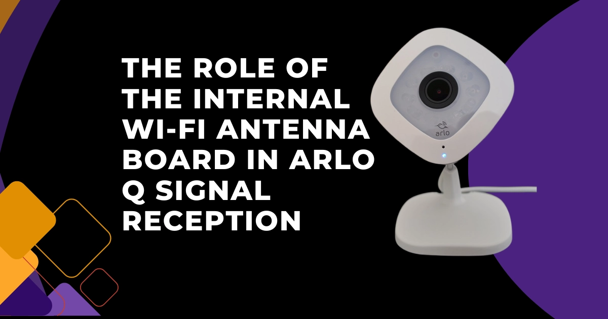
The Arlo Q’s Wi-Fi connectivity is not simply a matter of being “close enough” to a router. Everything the camera does, live streaming, motion recording, cloud storage upload, two-way audio, firmware updates, and app control is mediated through a single radio link between the Arlo Q’s internal Wi-Fi antenna and the user’s router or access point. The quality of this link, measured in signal strength (RSSI), determines not just whether the camera connects, but whether it maintains a stable connection during the high-bandwidth demands of 1080p video upload, whether it recovers quickly after a momentary signal interruption, and whether it can sustain continuous video recording without buffering gaps.
Understanding the Wi-Fi antenna architecture inside the Arlo Q, the antenna type, its physical orientation, the frequency bands it supports, and how the camera’s housing interacts with signal propagation provides the technical foundation for optimizing camera placement, diagnosing connectivity failures, and understanding the specific limitations of the Arlo Q in complex RF environments.
THE WI-FI CHIPSET AND ANTENNA BOARD: HARDWARE IDENTIFICATION
The Arlo Q’s Wi-Fi capability is implemented on a dedicated antenna board, a small PCB separate from the main logic board, connected via a coaxial RF cable or a direct PCB connector. This separate board design is used to position the antenna in the optimal location within the camera housing (typically near the exterior, away from metal shielding components) and to allow the antenna PCB to be produced with the precise layout tolerances that RF performance requires.
Wi-Fi standard: 802.11 b/g/n (Wi-Fi 4)
Supported frequency bands: 2.4 GHz only (the standard Arlo Q does not support 5 GHz)
Maximum theoretical throughput: 150 Mbps (802.11n single-stream on 2.4 GHz)
Security protocols: WPA, WPA2 (PSK)
Channel width: 20 MHz and 40 MHz HT modes
The 2.4 GHz-only specification is a hardware constraint; the chipset does not contain a 5 GHz radio. This is the same single-band architecture used in many contemporary IoT cameras and devices from the 2015-2017 era, chosen for the range advantage of 2.4 GHz in residential environments with multiple walls between camera and router.
ANTENNA DESIGN: PCB TRACE ANTENNA ARCHITECTURE
The Arlo Q’s Wi-Fi antenna is a PCB trace antenna, a specific antenna pattern etched directly onto the copper traces of the antenna board, rather than a discrete wire or rod antenna. PCB trace antennas are used in compact wireless devices for two primary reasons: they require no additional physical components (reducing cost and assembly complexity), and they can be designed to specific frequency and radiation pattern specifications through the trace geometry.
The antenna trace on the Arlo Q’s antenna board is configured for 2.4 GHz resonance (the trace length and geometry are calculated to be a fraction of the 2.4 GHz wavelength, approximately 12.5 cm, which creates efficient energy coupling between the trace and the electromagnetic field).
Radiation pattern:
A PCB trace antenna is not omnidirectional in the strict sense; it has a specific radiation pattern determined by the trace orientation and the ground plane on the PCB. The antenna transmits and receives most efficiently in directions perpendicular to its physical length and less efficiently along its axis. For the Arlo Q, this means the camera’s physical orientation (the direction it faces) affects the antenna’s coupling to the router not strongly enough to matter in most installations, but measurably in borderline signal scenarios.
HOW THE CAMERA HOUSING AFFECTS SIGNAL RECEPTION
The Arlo Q’s housing is made of ABS plastic, a material that is largely transparent to 2.4 GHz radio waves. This is ideal: the housing does not significantly attenuate the Wi-Fi signal passing through it. However, several other aspects of the housing and mounting configuration can affect signal reception:
Metal mounting plate proximity:
When the Arlo Q is mounted on its magnetic metal mounting plate, the ferromagnetic plate is in close proximity to the camera’s base, where the antenna board is typically positioned. Metal surfaces near an antenna affect its resonant frequency and radiation efficiency through a phenomenon called ground plane interaction. The mounting plate is small enough that this effect is minor rather than significant, but orienting the camera so the antenna board (at the top or rear of the housing, away from the metal plate) faces toward the router improves signal coupling in marginal installations.
Metal shelving or enclosures:
Placing the Arlo Q on a metal shelf directly against a metal back panel, or in a metal cabinet enclosure (for a server room or utility room deployment), significantly attenuates the Wi-Fi signal. Metal is highly reflective at 2.4 GHz; it blocks direct signal propagation and creates multipath interference patterns. The Arlo Q should be positioned with a clear line of sight to at least one direction toward the router.
Wall material between camera and router:
2.4 GHz signal attenuation per material:
- Drywall: 3–5 dB per layer
- Wood frame: 5–7 dB
- Brick: 10–14 dB per layer
- Concrete: 15–20 dB
- Metal (HVAC ducts, structural steel): 20–30+ dB
Each wall or obstacle reduces signal strength in dB. The Arlo Q requires an RSSI of approximately -70 dBm or better for reliable 1080p streaming. A router providing -50 dBm at the camera location has approximately 20 dB of margin, adequate for one to two concrete or brick walls.
RSSI AND BANDWIDTH: THE TWO DIMENSIONS OF WI-FI QUALITY
RSSI (Received Signal Strength Indicator) measures the power of the received Wi-Fi signal at the Arlo Q’s antenna. It is measured in dBm (decibels relative to 1 milliwatt), a negative number where values closer to zero indicate a stronger signal.
RSSI thresholds for Arlo Q performance:
50 dBm or better: Excellent. Full 1080p streaming, instant motion alerts, and reliable CVR without gaps.
50 to −65 dBm: Good. Reliable operation under normal conditions. Occasional brief buffering in CVR at peak household network usage.
65 to −75 dBm: Fair. 1080p streaming may reduce quality. CVR timeline gaps possible. Motion alerts may be delayed.
75 dBm and below: Poor. Frequent disconnections, recording failures, failed firmware updates, device offline errors.
RSSI alone does not determine connectivity quality; channel utilization (congestion) also matters. In a 2.4 GHz environment with many competing networks on the same channel (apartment buildings, dense suburban areas), even strong RSSI can produce poor throughput because the channel is congested with competing transmissions. The Arlo Q has no ability to measure channel utilization directly; the Arlo app’s signal strength indicator reflects RSSI only, not channel utilization.
THE 2.4 GHz BAND LIMITATION AND MODERN ROUTER CONFIGURATIONS
The Arlo Q’s 2.4 GHz-only Wi-Fi chipset creates a specific compatibility challenge with modern dual-band and mesh routers that manage band assignment automatically.
Smart Connect / Band Steering:
Many modern routers present a single SSID for both 2.4 GHz and 5 GHz bands and automatically assign devices to the optimal band. Since the Arlo Q cannot connect to 5 GHz, band-steered networks may attempt to assign it to 5 GHz and fail. The solution: disable Smart Connect and create separate SSIDs for each band, or ensure the Arlo Q is configured to connect to the explicitly labeled 2.4 GHz SSID.
Wi-Fi 6 (802.11ax) router compatibility:
Wi-Fi 6 routers maintain backward compatibility with 802.11 b/g/n clients on the 2.4 GHz band. The Arlo Q connects to Wi-Fi 6 routers on the 2.4 GHz band using the 802.11n protocol without any incompatibility. However, the Arlo Q will not benefit from Wi-Fi 6’s improved efficiency features (OFDMA, MU-MIMO); it connects as a legacy client.
WPA3 network security:
The Arlo Q’s Wi-Fi chipset firmware supports WPA2 but not WPA3. Routers set to WPA3-only mode prevent connection. WPA3 Transition Mode (supporting both WPA2 and WPA3 simultaneously) is compatible. The specific connectivity configuration issues for the Arlo Q, including 2.4 vs. 5 GHz band conflicts, channel configuration, and SSID setup, are covered in the companion guide How to Fix Arlo Q Connection Drops on 2.4GHz vs. 5GHz Dual-Band Networks.
DIAGNOSING ANTENNA BOARD HARDWARE FAILURE
Antenna board hardware failure is rare; the antenna PCB contains no moving parts and is not subject to wear. The most likely failure modes are:
Physical damage to antenna trace: Impact damage to the camera housing can crack the antenna PCB or break the trace pattern, effectively disabling the antenna. Symptoms: the camera cannot connect to Wi-Fi or consistently shows a very poor signal despite close proximity to the router. A functional Arlo Q held 3 feet from the router should show strong RSSI (-40 to -55 dBm); a camera with a broken antenna shows -80 dBm or below at the same distance.
RF cable disconnection: If the internal coaxial RF cable between the antenna board and the main chipset becomes disconnected (possible after a drop or mishandled disassembly), the antenna is electrically isolated from the Wi-Fi chipset. Symptoms are identical to a broken antenna trace.