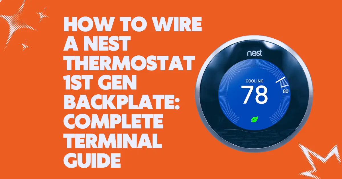
The backplate of the Nest Learning Thermostat 1st Generation is where the entire relationship between the thermostat and the HVAC system is established. It is a wall-mounted connector hub, a precisely engineered interface between the low-voltage 24VAC control wiring of the HVAC system and the computing logic of the Nest device. Every capability the Nest can offer heating control, cooling control, fan management, emergency heat, and, most critically, self-powering depends on which wires are connected to which terminals on this backplate. Understanding what each terminal does, which wires should connect to it, and what happens when a terminal is empty, wrongly used, or incorrectly wired is essential knowledge for installation, troubleshooting, and optimization of the Nest 1st Gen.
This guide covers every terminal on the Nest 1st Gen backplate, its electrical function, the HVAC system component it controls or connects to, compatibility considerations, and the direct consequences for Nest power behavior when each terminal is populated or empty.
THE BACKPLATE TERMINAL LAYOUT
The Nest 1st Gen backplate presents terminals in a circular arrangement around the central mounting point. The terminals are spring-loaded push-in connectors that accept standard thermostat wire (18–22 AWG) without tools; insert the stripped wire end, and the spring clamp secures it. A release button adjacent to each terminal allows wire removal.
Terminal labels on the Nest 1st Gen backplate:
| Rh – Red-Heat | 24VAC power from the heating transformer |
| Rc – Red-Cool | 24VAC power from the cooling transformer (separate transformer in some systems) |
| W – White | Heating control (calls the furnace or boiler) |
| W2 – White 2 | Second-stage heating control |
| Y – Yellow | Cooling control (calls the air conditioner compressor) |
| Y2 – Yellow 2 | Second-stage cooling control |
| G – Green | Fan control (calls the air handler blower independently) |
| C – Blue/Black | Common wire (return path for 24VAC transformer circuit) |
| O/B – Orange/Blue | Heat pump reversing valve control |
| E | Emergency heat |
| Aux | Auxiliary heat (backup heat in heat pump systems) |
Not all terminals will be populated in every installation; a simple forced-air heating-only system may use only Rh, W, and G, while a heat pump system may use Rh, Y, G, O/B, C, and Aux.
THE RH AND RC TERMINALS: UNDERSTANDING SPLIT TRANSFORMER SYSTEMS
Rh and Rc both provide 24VAC power to the thermostat; they are the “hot” side of the transformer circuit(s). In the majority of residential systems, a single transformer powers both the heating and cooling systems, and both Rh and Rc receive the same voltage from the same source. In these installations, a jumper wire connects Rh and Rc internally on the old thermostat (or the Nest’s backplate bridges them automatically in some configurations).
In dual-transformer systems, less common, typically found in older homes or commercial-grade residential systems, separate transformers power the heating and cooling circuits independently. Rh receives 24VAC from the heating transformer, and Rc receives 24VAC from the cooling transformer. These are electrically isolated circuits; connecting wires between them without understanding the isolation can cause a transformer short.
The Nest 1st Gen handles this correctly when wires are connected to both Rh and Rc separately; it isolates the circuits internally. When only one transformer exists, wiring should go to Rh (or Rc, depending on the original thermostat’s labeling) and the other terminal left empty.
THE C TERMINAL: THE MOST CONSEQUENTIAL TERMINAL FOR NEST OPERATION
The C-wire terminal (labeled C on the Nest backplate, typically wired with a blue or black wire) is the common return path for the 24VAC transformer circuit. It is the terminal that most directly determines whether the Nest 1st Gen can power itself reliably.
Why the C-wire is critical for the Nest specifically
Traditional thermostats were passive switches; they drew negligible current from the HVAC wiring and had no need for a dedicated power return path. The C-wire existed in many HVAC systems but was never connected at the thermostat because it wasn’t needed.
The Nest 1st Gen is an active computing device that continuously draws current. For this current to flow steadily, a complete circuit is required: current flows from the transformer’s 24VAC hot side through the Rh wire to the Nest, does work (powering the Nest), and must return to the transformer through a return path, the C-wire. Without a C-wire, no complete steady-state circuit exists, and the Nest must resort to power stealing using brief, intermittent current pulses through the HVAC control wires to charge its battery.
Power stealing has two documented problems
1. Incompatibility with some HVAC systems: Electronic air handlers, variable-speed furnaces, and certain heat pumps respond to the brief current pulses of power stealing by activating or going into fault states; the HVAC system “sees” a call for heating or cooling when none was intended.
2. Insufficient charging in high-activity scenarios: Power stealing delivers less average current than a C-wire connection. In cold climates with long heating cycles, the Nest’s demand for display power, Wi-Fi transmission, and sensor monitoring can exceed what power stealing delivers, causing the battery to slowly deplete.
Identifying whether a C-wire is available
Locate the HVAC air handler or furnace. Open the control board access panel. The 24VAC transformer secondary terminals are visible, typically labeled R/C or R/Com. Count the wires going to the thermostat wire bundle. If there are 5 or more wires and one is currently not connected at the thermostat (tucked behind the backplate), that is the available C-wire.
THE W TERMINAL: HEATING CONTROL
The W terminal (white wire) is the heating call signal. When the Nest determines that heating is needed, it closes an internal relay that connects the Rh terminal to the W terminal, completing the 24VAC circuit through the furnace’s heating control board, signaling the furnace to fire.
W2 is used for two-stage heating systems where a second, higher-capacity heating stage is available. The Nest 1st Gen supports two-stage heating when W2 is wired it activates W2 when the first stage has been running for a configured duration without reaching setpoint.
THE Y TERMINAL: COOLING CONTROL
The Y terminal (yellow wire) signals the air conditioning compressor to activate. When the Nest calls for cooling, it connects Rc to Y, closing the contactor on the outdoor condensing unit and starting the compressor. The G terminal (fan) is typically also activated simultaneously, though independent fan control (running the fan without cooling) is possible via the G terminal alone.
THE O/B TERMINAL: HEAT PUMP REVERSING VALVE
Heat pumps require a reversing valve control wire (O or B, depending on manufacturer convention) that switches the refrigerant circuit between heating and cooling modes. The Nest 1st Gen’s O/B terminal handles both conventions:
- O convention (most US brands Carrier, Lennox, Trane, Rheem): The valve is energized (24VAC applied) in cooling mode.
- B convention (Heat Controller, some older brands): The valve is energized in heating mode.
During Nest setup, the user selects the O or B convention for their specific heat pump; this determines when the Nest applies voltage to the O/B terminal.
TERMINAL CONFIGURATION AND ITS DIRECT EFFECT ON NEST POWER SYMPTOMS
The relationship between terminal configuration and Nest power behavior is direct and predictable:
Rh only, no C-wire → Power stealing mode: Adequate for simple 2-wire systems (heat only) in mild climates; inadequate for complex systems or cold climates. Device may show “delayed start” behavior and battery warnings.
Rh + C-wire → Continuous trickle charge: Reliable power delivery for all activity levels. No power-related symptoms in a functional installation.
Rh only, complex system (multiple control wires) → Power stealing interference: The additional control wires provide additional stealing opportunities but also increase the risk of false HVAC activation signals.
No Rh and no Rc → No power at all: The Nest cannot operate.
The full diagnostic process for identifying which wiring scenario applies to a specific installation, and the solutions for each, is detailed in the companion guide Nest 1st Gen Showing “No Power” to Rh or Rc Wires: Step-by-Step Diagnostics.
WIRE INSERTION AND REMOVAL: MECHANICAL DETAILS
Each terminal on the Nest 1st Gen backplate uses a spring-loaded jaw mechanism:
Insertion: Strip approximately 10mm of insulation from the wire end. Press the stripped copper end straight into the terminal port until it stops. The spring jaw engages automatically.
Confirmation: A correctly inserted wire holds firmly against a gentle pull.
Removal: Press the orange release button adjacent to the terminal with a small screwdriver while pulling the wire gently backward.
Do not over-strip the wire: bare copper extending outside the terminal port can bridge between adjacent terminals, creating short circuits or cross-connections that cause erratic HVAC behavior.