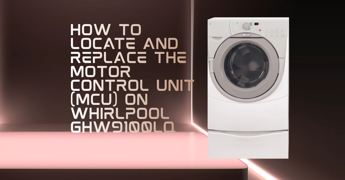
The Motor Control Unit in the Whirlpool GHW9100LQ Duet washer is the power electronics board responsible for controlling the AC induction motor that drives the drum. The Central Control Unit (CCU) determines when the motor should run, at what speed, and in which direction, but it is the MCU that actually delivers the variable-frequency AC power to the motor windings to make this happen. Without a functional MCU, the GHW9100LQ’s motor cannot run regardless of how correctly the CCU issues its commands, and the machine cannot complete any cycle that requires drum movement.
The MCU is one of the more commonly replaced components on the GHW9100LQ platform, and it is frequently misidentified; owners and technicians sometimes replace the CCU when the MCU is the actual failure point, because both produce similar “machine won’t run” symptoms. This guide provides the complete diagnostic confirmation procedure, the physical location and access procedure, and the full replacement steps.
UNDERSTANDING THE MCU’S ROLE IN THE DRIVE SYSTEM
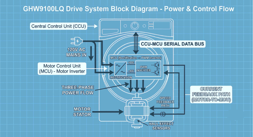
The GHW9100LQ’s motor is an AC induction motor that requires variable-frequency AC voltage to control its speed. A standard 60 Hz household AC supply drives the motor at one fixed speed; this is not suitable for a washer that needs to tumble at 47 RPM during wash and spin at 1,000 RPM during extraction. The MCU solves this by:
1. Rectifying the 120V AC supply to DC
2. Using a PWM (Pulse Width Modulation) inverter bridge to synthesize AC at a controlled frequency
3. Delivering this synthesized variable-frequency AC to the motor stator windings
4. Monitoring the motor’s operational current, speed feedback, and temperature
The MCU receives speed and direction commands from the CCU via the serial communication bus. It executes these commands and reports back motor status, current draw readings, and any fault conditions it detects independently. When the MCU detects an abnormal condition (overcurrent, overvoltage, overtemperature, or motor stall), it can independently generate a fault code and halt motor operation even before the CCU requests a stop.
MCU IDENTIFICATION AND PART NUMBERS
Primary OEM part number: WP8183196 (current Whirlpool service replacement)
Cross-reference part numbers: 8183196, AP3866731, PS991463
Compatible models: GHW9100LQ, GHW9100LW, and related first-generation Duet models (verify by full model number before ordering)
Physical identification:
The MCU is a larger board than the CCU, approximately 10 × 6 inches (25.4 × 15.2 cm), mounted at the base of the machine’s interior, typically secured to the bottom frame or lower-front chassis, behind the front access panel. It is identifiable by the large power transistors or IGBT modules mounted on a heatsink (for thermal management of the high-current switching components), the large filter capacitor on the DC bus, and the three-phase output wiring that connects to the motor stator.
The MCU has two primary connector groups:
Low-voltage connector: the serial communication bus and control signal interface connecting to the CCU harness
High-voltage connectors: 120V AC power input from the mains supply, and three-phase AC output to the motor
FAULT CODES INDICATING MCU FAILURE
The following fault codes specifically implicate the MCU as the failure source (as distinct from the CCU or the motor itself):
F03 (E300)
Voltage drop or brownout detected by the MCU: the DC bus voltage in the MCU’s rectifier circuit dropped below the minimum threshold. Indicates MCU power supply failure or line voltage inadequacy.
F05 (E500)
NTC thermistor circuit open or short in MCU. The MCU’s internal temperature sensor has failed. The MCU cannot self-monitor for overtemperature.
F06 (E600)
MCU error: the MCU has detected an internal fault. This is the most definitive MCU-failure fault code.
F07 (E700)
Motor control fault: the MCU detected that the motor is not responding to control signals as expected. Can indicate MCU output stage failure or motor failure.
F08 (E800)
Door heat failure reported via MCU communication
Additionally, F11 (serial communication error between CCU and MCU) can be caused by either the CCU’s serial output, the interconnecting harness, or the MCU’s serial input. F11 is not exclusively an MCU fault code; both boards must be evaluated when F11 appears.
ACCESSING THE MCU: DISASSEMBLY PROCEDURE
Required tools:
- Phillips-head screwdriver (PH2)
- Flat-head screwdriver (small)
- Nut driver (1/4-inch hex)
- Needle-nose pliers (for connector release tabs)
- Multimeter (for pre-replacement fault confirmation)
Safety: Unplug the washer from the wall outlet before any disassembly. The MCU handles mains voltage (120V AC) and high-voltage DC from its internal rectifier — residual charge can remain in the DC bus capacitor for up to several minutes after unplugging. Wait 5 minutes after unplugging before touching the MCU board or its high-voltage wiring.
Step 1 – Remove the front access panel
The GHW9100LQ’s lower front access panel (below the door opening) is secured by two or three screws at its base. Remove these screws and pull the panel bottom outward and down to disengage its top tabs from the front frame. Set the panel aside.
Step 2 – Locate the MCU
With the front panel removed, the MCU is visible in the lower cavity of the machine. It is mounted horizontally, with its heatsink surface facing downward or toward the front of the machine for cooling airflow. The large filter capacitor (a cylindrical electrolytic capacitor, approximately 25–35mm diameter) is prominently visible on the board.
Step 3 – Photograph all connections
Before disconnecting anything, photograph the MCU from multiple angles to document the harness connector positions, routing, and locking tab orientations. The MCU has at least four connectors; detailed documentation prevents reassembly errors.
Step 4 – Disconnect the low-voltage communication harness
This small multi-pin connector (typically 5–8 pins) connects the MCU to the CCU via a thin ribbon or wire harness. Squeeze the locking tab and pull the connector straight out.
Step 5 – Disconnect the AC power input connector.
This is the mains voltage input to the MCU a 2-pin or 3-pin connector with heavy-gauge wire (12 or 14 AWG). Squeeze the locking tab and disconnect. Confirm the wire ends are not live (machine is unplugged and wait time has elapsed).
Step 6 – Disconnect the motor output connector.
This is the three-phase AC output, three wires (typically black, white, red or three matching colors) connecting the MCU output terminals to the motor stator. Each connection may be individual spade terminals or a single 3-pin connector depending on production variant.
Step 7 – Remove mounting screws and remove the MCU
The MCU is secured by 3-4 screws to the chassis mounting bracket. Remove these screws and lift the MCU free.
INSTALLING THE REPLACEMENT MCU
Install the replacement MCU in the reverse order of removal. Critical installation points:
Heatsink thermal interface
If the MCU’s heatsink makes contact with a chassis thermal pad or thermal interface material, ensure this interface material is intact. Heat transfer from the MCU’s power transistors to the chassis is important for thermal management during high-speed spin cycles.
Connector polarity
All connectors on the GHW9100LQ MCU are keyed; they can only be inserted in the correct orientation. Do not force any connector; if it does not seat easily, confirm it is correctly aligned before applying pressure.
Torque on mounting screws
Tighten mounting screws to snug-firm torque; the MCU mounting affects thermal contact and vibration resistance. Do not overtighten the PCB mounting; bosses can crack under excessive screw torque.
POST-REPLACEMENT TESTING
After reassembly, run the washer through a short test cycle (Normal cycle with no laundry) and confirm:
- The drum tumbles during the wash phase (confirms MCU is delivering low-speed drive to motor)
- The drum spins during the spin phase (confirms MCU is delivering high-speed drive)
- No fault codes appear on the display
- The MCU area does not produce unusual heat (confirm the heatsink is not running excessively hot after a 5-minute run)
If the spin issue persists after MCU replacement, the drive belt or motor itself should be evaluated. The spin-no-spin diagnostic, including how to distinguish MCU from belt from motor faults, is covered in the companion guide Why Your Whirlpool Duet GHW9100LQ Won’t Spin (MCU vs. Drive Belt Check).