The water inlet valve assembly on the Whirlpool GHW9100LQ controls the entry of both hot and cold water into the machine during the fill phases of every wash cycle. It is a multi-solenoid electromechanical valve assembly with separate coils for hot water, cold water, and the dispenser, each controlled independently by the Central Control Unit (CCU). When the fill valve functions correctly, it delivers precise amounts of water at the correct temperature for each wash cycle phase. When it fails, whether from solenoid burnout, scale clogging, or screen filter blockage, the result ranges from a machine that fills too slowly to one that fails to fill at all, triggering the FH or F20 water inlet fault code.
Understanding the inlet valve’s construction, electrical specifications, flow rate parameters, and the maintenance schedule for its screen filters is the foundation for diagnosing and resolving every fill-related problem on the GHW9100LQ.
INLET VALVE IDENTIFICATION AND PART NUMBERS
Assembly part number: WP8181694 (current Whirlpool service replacement)
Cross-reference part numbers: 8181694, AP3866543, PS990420
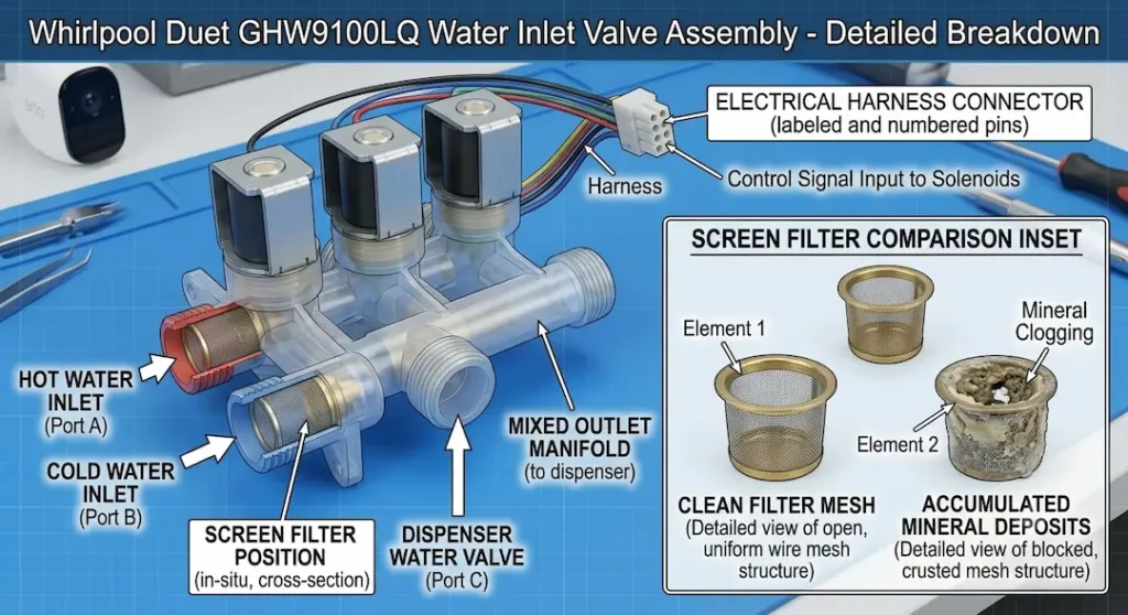
Number of solenoid valves in assembly: 3 (hot inlet, cold inlet, dispenser/internal routing)
Water connection type: 3/4-inch female garden hose thread on both hot and cold inlets
Operating pressure range: 20-100 PSI supply pressure; 30-60 PSI optimal for correct flow rates
The three-valve construction is specific to the GHW9100LQ’s HE (High Efficiency) wash system: the third valve routes water through the dispenser housing for detergent and fabric softener dilution before delivering it to the drum. This architecture is distinct from simpler inlet valves that deliver water directly without dispenser routing.
SOLENOID ELECTRICAL SPECIFICATIONS
Each solenoid in the assembly is an electromagnetic coil that, when energized by the CCU, opens the valve’s rubber diaphragm against water pressure. When de-energized, the diaphragm’s spring force and water pressure close the valve.
Solenoid coil resistance (each valve): approximately 200–400 ohms at room temperature
Operating voltage: 120V AC (the CCU switches line voltage through relay contacts to energize each solenoid)
Current draw per solenoid: approximately 0.25–0.5A when energized
Response time: less than 0.5 seconds from energization to full flow
The resistance specification is important for testing a solenoid coil; outside the 200-400 ohm range (particularly an open circuit / infinite resistance reading) indicates a burned-out coil that will not open the valve.
FLOW RATE SPECIFICATIONS
The flow rate through each valve determines how quickly the drum fills with water. The GHW9100LQ’s fill timing is calibrated to the expected flow rate if the actual flow rate is significantly below specification (from screen clogging or low supply pressure), the CCU times out the fill phase before adequate water has entered the drum, generating an FH or F20 fault code.
Rated flow rate (at 60 PSI supply pressure, each valve): approximately 1.0–2.0 gallons per minute (GPM)
Minimum required flow rate for reliable fill: approximately 0.5 GPM (below this, the CCU fill timeout is exceeded before the water level sensor registers the target level)
Shut-off pressure: the diaphragm seals completely at pressures below approximately 1 PSI, preventing backflow
The relationship between supply pressure and flow rate follows the expected hydraulic relationship: higher supply pressure produces higher flow rate through the fixed orifice of the valve. At 30 PSI (the minimum recommended), flow rate is approximately 60-70% of the 60 PSI rated flow. At 20 PSI (absolute minimum), flow rate may be insufficient for reliable fill timing.
THE INLET SCREEN FILTERS: FUNCTION AND MAINTENANCE
Each of the hot and cold water inlets on the valve assembly is protected by a fine mesh screen filter a cylindrical or flat mesh screen pressed into the inlet port. These screens filter particles from the household water supply before they can reach the solenoid’s diaphragm seat. A particle lodged in the diaphragm seat prevents the valve from fully closing, causing continuous water flow into the drum even when the valve should be closed (a slow fill that continues during the spin cycle, for example).
Over years of use, these screens accumulate mineral deposits (particularly in hard water areas), sediment, and debris. A heavily clogged screen reduces flow rate dramatically, often below the minimum required for reliable fill operation, while the solenoid coil itself remains fully functional.
Screen filter specification: approximately 50-100 mesh (150-300 micron filtration)
Typical maintenance interval: inspect every 1-2 years; clean when visible sediment is present or when FH/F20 codes appear without other inlet valve fault
Cleaning procedure
1. Shut off both hot and cold supply valves. Disconnect the supply hoses from the inlet valve.
2. Using needle-nose pliers, carefully grip and pull the mesh screen from each inlet port. Apply straight axial force; the screens are press-fitted and pull out cleanly without tools on most production variants.
3. Rinse the screens under running water to remove loose sediment. For mineral deposits, soak in white vinegar (acetic acid) for 15-30 minutes to dissolve calcium carbonate deposits.
4. Inspect the screen mesh for holes or tears. A damaged screen must be replaced rather than reinstalled (a torn screen provides no filtration and allows particles to reach the valve seat).
5. Reinsert the screens, reconnect the supply hoses with new rubber sealing washers, and restore water supply. Check for leaks at all connections before running the machine.
The screen cleaning procedure directly addresses the complaint described in the companion guide Whirlpool GHW9100LQ Fails to Fill with Water: Troubleshooting Inlet Screen Clogs.
TESTING THE INLET VALVE
Test 1 – Solenoid continuity test:
Disconnect the water inlet valve harness connector. With a multimeter set to resistance measurement, test each solenoid pair of pins at the connector:
- Hot valve solenoid: measure between pins 1 and 2 (connector pinout varies; confirm against wiring diagram)
- Cold valve solenoid: measure between pins 3 and 4
- Dispenser valve solenoid: measure between pins 5 and 6
Expected: 200-400 ohms at room temperature for each coil.
Open circuit (OL): coil has burned out; valve assembly replacement required.
Near-zero ohms: coil has an internal short; valve assembly replacement required.
Test 2 – Valve operation confirmation (live test)
With the supply hoses connected and the machine in a fill cycle, each solenoid should be audibly active when energized a distinct click when it opens and closes. If a specific valve (hot only, cold only, or dispenser only) fails to activate, the fault is isolated to that solenoid coil or the CCU relay that energizes it.
Test 3 – Valve closure confirmation:
After cycle completion, no water should drip or flow from the drum. Slow or continuous post-cycle dripping while the machine is idle indicates a valve that is not sealing completely, likely from a particle on the diaphragm seat or a diaphragm that has lost its elasticity.
FAULT CODES RELATED TO THE WATER INLET VALVE
FH (also displayed as F9 E1 on some variants)
No water detected during fill. Causes: supply water valves closed, failed inlet valve solenoid, blocked screen filters, failed water level pressure switch, or pressure switch hose kinked.
F20 (or F/20)
Water inlet problem; similar interpretation to FH; specifically relates to the fill timing exceeding expected duration.
The water level pressure switch is the sensor that tells the CCU when enough water has filled the drum if the pressure switch fails to signal fill completion, the CCU generates these codes even with a perfectly functional inlet valve. Diagnosing whether the FH/F20 code is from the valve or the pressure switch requires isolating each. The pressure switch specifications and testing procedure are in the companion guide How the Analog Water Level Pressure Switch Works in Whirlpool GHW9100LQ.
VALVE REPLACEMENT PROCEDURE
1. Shut off both water supply valves. Unplug the washer.
2. Disconnect both supply hoses from the old valve. Place towels to catch residual water.
3. Remove the top panel of the washer (typically 2-3 screws at the rear of the top panel, then slide the panel backward and lift).
4. The inlet valve assembly is mounted at the rear of the top cavity, adjacent to the water inlet hoses. Remove the 2-3 screws securing it to the chassis.
5. Disconnect the internal outlet hoses from the valve (these route water to the dispenser and drum) and the electrical harness.
6. Install the replacement valve in reverse order, confirming each outlet hose is correctly routed (hot outlet to hot hose, cold outlet to cold hose, dispenser outlet to dispenser hose).
7. Reconnect supply hoses with fresh rubber sealing washers.
8. Restore water and power. Run a fill test and check all connections for leaks.