The infrared dust sensor in the Levoit Core 200S is the component responsible for the air quality indicator light, the three-color LED ring (Blue/Orange/Red) that communicates the unit’s real-time assessment of particulate levels in the surrounding air. It is also the component that drives Auto mode fan speed adjustment: when the sensor reads elevated particle density, the fan accelerates; when it reads clean air, the fan reduces speed or enters Sleep mode. For a machine whose defining feature is smart, responsive air quality management, the sensor that informs every autonomous decision is a critical component, and it is one that fails silently and gradually when it accumulates dust on its optical surfaces.
This guide explains the sensor’s operating principle, its precise location on the Core 200S, why and how it accumulates contamination, and the correct cleaning procedure for restoring accurate readings.
HOW THE INFRARED DUST SENSOR WORKS: OPTICAL LIGHT SCATTER PRINCIPLE
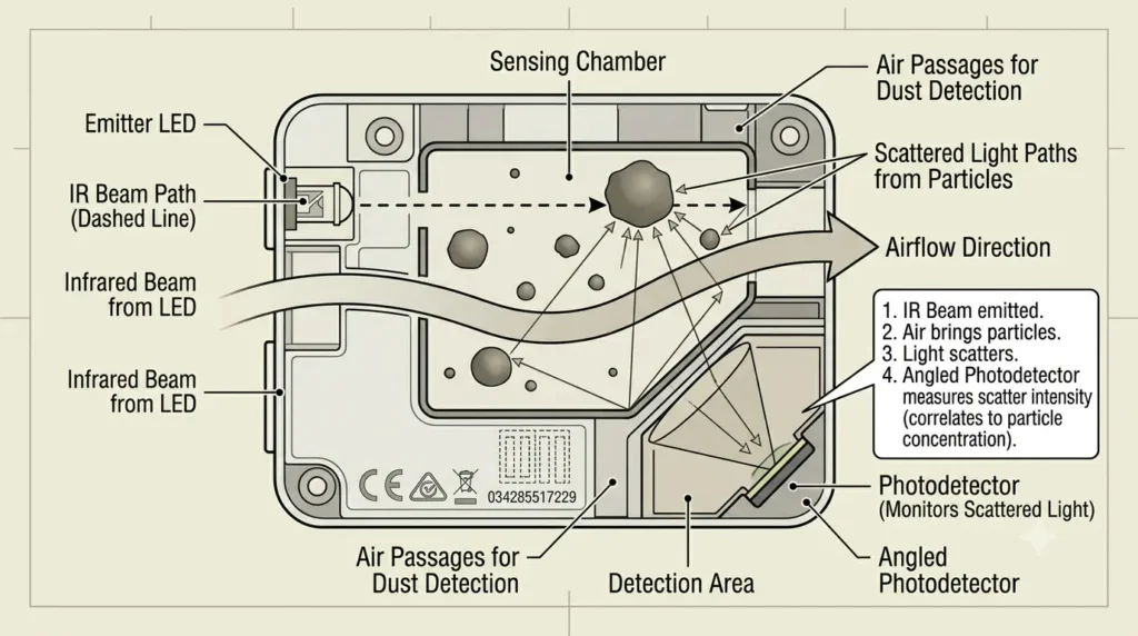
The Core 200S uses an infrared (IR) optical particle sensing technique based on light scatter. The sensor assembly contains two primary components within a small housing: an infrared LED emitter and a photodetector (photodiode or phototransistor).
The emitter projects a focused beam of infrared light across the interior of the sensing chamber. The detector is positioned at an angle not directly opposite the emitter, but at a side angle that places it outside the emitter beam path. Under clean air conditions, the IR beam crosses the chamber without being scattered, and the detector receives minimal light (since it is not in the direct beam path).
When air containing particles passes through the sensing chamber, particles in the beam path scatter the IR light in multiple directions, including toward the angled detector. The detector produces an electrical signal proportional to the intensity of scattered light it receives. The sensor’s onboard electronics process this signal and output a qualitative classification (low/medium/high particle density) that the Core 200S MCU maps to the Blue/Orange/Red indicator states.
This is a single-channel infrared scatter measurement; it does not discriminate between particle sizes or provide a calibrated PM2.5 or PM10 mass concentration reading. It estimates relative particle density and outputs a threshold-based classification. This is functionally adequate for Auto mode operation (the fan should run faster when there are more particles), but is not suitable for precision air quality measurement.
LOCATING THE SENSOR ON THE CORE 200S
The infrared dust sensor is located on the lower rear section of the Core 200S outer housing, the cylindrical outer shell, positioned between the air intake slots. Its location on the exterior of the housing (rather than the interior) is a deliberate design choice: by positioning the sensing chamber at the point of air intake, the sensor samples air as it enters the unit before it passes through the filter. This allows the sensor to detect the particle concentration in the room air, not the (already-filtered) air inside the machine.
Physical identification:
The sensor is identifiable from the exterior by a small rectangular or circular port opening approximately 8 to 15 mm in the longest dimension visible on the rear lower surface of the outer cylindrical housing. The port has a small plastic shroud or hood that partially shields the sensing chamber opening from direct light and from airborne debris entering at low angles. On some Core 200S production variants, the sensor port is covered by a semi-transparent plastic window that protects the optical components while allowing ambient air access.
The sensor connects internally to the main PCB via a small multi-wire harness (typically 3 to 5 wires: power supply, ground, and signal output(s)).
HOW THE SENSOR BECOMES CONTAMINATED
The sensing chamber’s position at the air intake path makes it inherently vulnerable to dust accumulation. Every particle that the sensor detects passes through the sensing chamber. While most particles continue into the unit and are captured by the filter, some deposit on the internal surfaces of the sensing chamber: the emitter lens, the photodetector window, and the reflective surfaces of the chamber walls.
Three contamination patterns are common:
Pattern 1: Gradual fine dust film on optical surfaces
Over months of operation, fine particulate matter (sub-10 micron particles) accumulates as a thin film on the emitter LED lens and the photodetector window. This film attenuates the IR beam before it reaches the sensing chamber and attenuates scattered light before it reaches the detector. The net effect: the sensor underreads particle density, it reports cleaner air than is actually present, causing the indicator to show Blue and Auto mode to select low fan speeds even when particle levels are elevated.
Pattern 2: Fiber/hair obstruction at the chamber inlet
Pet hair, textile fibers, and lint can lodge at the sensing chamber inlet port, partially blocking the air pathway through the chamber. This reduces the volume of air sampled per unit time and can also scatter IR light at the inlet, creating a persistent false positive signal. The indicator stays at Orange or Red even in clean air because the fiber in the inlet port continuously scatters the IR beam toward the detector.
Pattern 3: Oil/grease film accumulation
In kitchens or environments with cooking aerosols, airborne grease particles accumulate in the sensing chamber as an optically refractive film. This film both scatters and absorbs the IR beam, producing inconsistent and unreliable readings. A grease film in the sensing chamber is more adhesive than a dry dust film and requires isopropyl alcohol for effective cleaning.
SYMPTOMS OF A CONTAMINATED SENSOR
Before performing any sensor cleaning, confirm that the sensor contamination (rather than genuinely poor air quality) is producing the observed symptom:
Persistent Red/Orange indicator in clearly clean conditions: If the indicator remains Orange or Red in a room with no obvious particle sources, no recent cooking or smoke events, and the window has been open with clean outdoor air, and if the symptom persists across multiple hours, the sensor is likely reading falsely high due to a fiber obstruction or chamber contamination.
Indicator stuck on Blue regardless of actual conditions: If cooking smoke, candle burning, incense, or a nearby dusty event fails to trigger any indicator change or fan speed increase in Auto mode, the sensor is underreading due to optical surface contamination.
Air quality indicator behavior disconnected from VeSync app data: If the physical LED indicator disagrees with the app’s air quality display (which reads from the same sensor data), there is a communication issue rather than a sensor contamination issue. The sensor hardware and firmware processing are in the signal chain between physical measurement and both displays.
The causes and solutions for a persistently stuck indicator are also addressed in the companion guide Why is the Air Quality Indicator Light Stuck on Red/Orange on Core 200S?, which covers both sensor contamination and firmware/calibration causes.
CLEANING THE SENSOR: STEP-BY-STEP PROCEDURE
The infrared dust sensor can be cleaned without disassembling the Core 200S housing; the sensing chamber inlet port is accessible from the exterior. Full internal cleaning of the sensor optical surfaces (emitter lens and detector window) requires partial disassembly, but the majority of sensor contamination problems are resolvable with the exterior-accessible cleaning procedure.
Exterior cleaning (no disassembly required):
Tools needed: Compressed air canister, soft-bristle brush (clean toothbrush), cotton swabs, isopropyl alcohol (90%+), flashlight.
Step 1: Power off and unplug the Core 200S.
Step 2: Locate the sensor port on the rear lower housing. Shine a flashlight into the port to illuminate the sensing chamber interior. Look for visible debris (fiber, lint, accumulated dust) at the chamber inlet.
Step 3: Use a short burst of compressed air directed into the sensor port to dislodge loose dust and debris from the chamber interior. Orient the nozzle at a low angle relative to the port, not perpendicular into the port, which can push debris further into the sensing chamber, but at an angle that creates a sweeping airflow across the chamber interior.
Step 4: Use the soft-bristle brush to gently clean the exterior of the port opening and the protective shroud. Do not insert the brush deeply into the port; the brush is for the port periphery, not the optical surfaces inside.
Step 5: Inspect with the flashlight again. If visible debris remains inside the chamber, use a cotton swab slightly dampened with isopropyl alcohol inserted gently into the port opening to reach the near surfaces of the chamber. The swab should make light contact with the chamber walls, emitter lens face, and detector window, using a gentle circular motion and minimal pressure.
Step 6: Allow the chamber to air dry for 2 to 3 minutes before powering on (isopropyl alcohol evaporates quickly, but allowing complete evaporation before applying power is good practice).
Step 7: Power on, set to Auto mode, and observe the indicator behavior. In a normally clean room with no active particle sources, the indicator should settle to Blue within 2 to 5 minutes. Test the sensor response by briefly generating a small particle source near the intake (incense stick held several feet away, lightly shaken dusty item) and confirming the indicator transitions to Orange or Red and fan speed increases.
SENSOR CLEANING FREQUENCY
The infrared dust sensor does not have an explicit maintenance interval in Levoit’s documentation. A practical cleaning frequency based on the operating environment:
Standard residential: Every 3 to 4 months, incorporated into the pre-filter cleaning session.
Kitchen environment or near cooking surfaces: Every 4 to 6 weeks. Grease aerosol accumulates significantly faster than dry dust in the sensing chamber.
High-dust or pet-heavy environment: Every 6 to 8 weeks.
Wildfire smoke events: Clean the sensor after any multi-day period of heavy smoke exposure. Fine smoke particles accumulate rapidly on optical surfaces and produce persistent indicator errors after the smoke clears.
SENSOR REPLACEMENT
If cleaning does not resolve the inaccurate indicator behavior, the sensor itself may have failed, the IR LED electronically has burned out, the photodetector has degraded, or the onboard signal processing circuit has failed. Sensor failure produces a constant fixed-state indicator (always Blue regardless of conditions, or always Red regardless of conditions) that does not respond to any obvious particle source, even after thorough cleaning.
Replacement sensors compatible with the Core 200S are available from electronics component suppliers. The sensor module is a small self-contained unit (commonly GP2Y1010AU0F or a similar module in this product class) that connects via a 6-pin harness. Replacement requires soldering or harness connector work and basic PCB-level assembly skills.