
The internal fan blades of the Levoit Core 200S are not a maintenance item that Levoit’s user documentation addresses; the official manual covers filter replacement and exterior cleaning only. Yet the centrifugal impeller inside the unit accumulates dust and debris over months of operation, and this accumulation has measurable consequences for both airflow performance and noise. Understanding why the fan blades load with dust, how to safely access them without damaging the unit, how to clean them correctly, and how to verify the impeller is balanced after reassembly constitutes a meaningful extension of the Core 200S’s service life and performance ceiling.
This guide covers every step of internal fan blade access and cleaning intended for owners who are comfortable with basic appliance disassembly and want to perform maintenance beyond the filter replacement cycle.
WHY INTERNAL FAN BLADES ACCUMULATE DUST
The Levoit Core 200S filtration system is designed to capture particles before they reach the fan. The pre-filter, HEPA layer, and carbon layer are all positioned between the air intake and the motor/fan assembly. In theory, the air that reaches the fan blades has already been cleaned of all particulate matter. In practice, this is not perfectly true for two reasons:
1. Filter bypass around imperfect seals
Even a well-installed filter creates a near-perfect but not absolute seal against the housing. Ultrafine particles, those below 0.1 microns, and particles introduced during filter changes (when the filter is briefly removed and reinstalled) have pathways around or through the filter-housing interface. Over many months and multiple filter cycles, a thin but measurable layer of fine dust accumulates on the impeller blades.
2. Initial operation before first filter installation
Briefly operating the unit without a filter, even for a few seconds, introduces unfiltered ambient air directly to the fan, depositing a disproportionate amount of dust on the blade surfaces relative to filtered operation time. This is a common source of early fan blade loading.
The consequence of blade dust accumulation:
Centrifugal impellers are dynamically balanced from manufacture the mass distribution around the rotation axis is engineered to minimize vibration at operating speeds. When dust deposits unevenly on the blade surfaces (as it typically does, because air turbulence patterns near the blades are not perfectly symmetric), the mass balance of the impeller shifts. An unbalanced impeller vibrates at its rotation frequency, which increases noise, transmits vibration to the housing, and increases bearing wear in the motor. Additionally, dust-loaded blades have altered aerodynamic profiles, and blade thickness increases unevenly, which reduces the blade’s ability to accelerate air efficiently, decreasing CADR.
SAFETY AND PREPARATION
Before beginning any internal disassembly:
Power off completely: Long-press the power button (2 seconds) until the unit powers down. The illuminated LED indicator confirms the off state. Then unplug the power cord from the wall outlet. Do not proceed with a plugged-in unit under any circumstances. The BLDC motor controller can resume motor operation unexpectedly if the MCU receives a spurious signal during disassembly.
Allow cooling time: If the unit has been running recently, allow 10 minutes of unplugged rest. The motor and power supply PCB retain heat, which makes component handling uncomfortable.
Work surface: A clean, flat, well-lit work surface. A large sheet of white paper or a white cloth helps make small dropped components visible.
Tools required:
- Phillips-head screwdriver (PH1 or PH2 confirm against the actual screw size before beginning)
- Flat-head screwdriver (small, for prying plastic clips if needed)
- Soft-bristle brush (clean, dry toothbrush or electronics cleaning brush)
- Compressed air canister
- Isopropyl alcohol (90%+ concentration) and cotton swabs
- Flashlight or headlamp for internal visibility
- Small container for screws
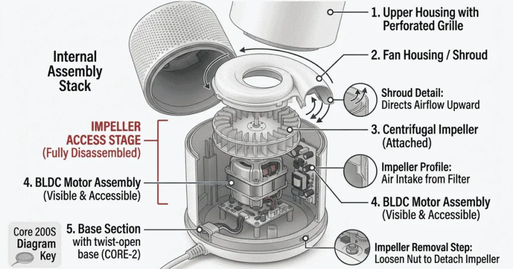
DISASSEMBLY SEQUENCE: ACCESSING THE FAN BLADES
The Core 200S is not designed for user-serviceable internal access; there are no toolless access panels to the fan assembly. Reaching the impeller requires separating the upper housing from the internal chassis assembly. The disassembly sequence below applies to the standard Core 200S production variant; minor variations exist across production runs.
Step 1: Remove the filter assembly
Rotate the base counterclockwise approximately 30 degrees and separate it from the upper housing. Remove the filter assembly from the base section and set it aside. This reveals the interior of the base section, which houses the motor and impeller.
Step 2: Identify the housing separation points
With the filter removed, inspect the interior of the base section for screws securing the motor housing assembly to the outer base shell. These are typically 2 to 4 Phillips-head screws visible at the bottom interior of the base section when viewed from the open top. Some variants also have a central screw accessible through the base exterior.
Step 3: Remove housing screws
Use the appropriate Phillips screwdriver to remove all visible interior screws. Place them in the small container immediately. Do not lose track of the screw count. Reassembly with a missing screw can leave the housing with insufficient clamping and introduce vibration.
Step 4: Separate the motor chassis from the outer housing
With screws removed, the motor/fan chassis assembly should be separable from the outer cylindrical housing. This separation is typically assisted by plastic alignment clips that require gentle inward pressure to release. Use a small flat-head screwdriver at the clip locations, pressing the clip inward while pulling the chassis upward. Do not pry aggressively; the clips are designed to release with moderate force, and excessive force cracks the housing.
Step 5: Access the centrifugal impeller
With the motor chassis separated, the centrifugal impeller is visible as a multi-blade wheel mounted directly on the motor shaft. The impeller sits inside a volute (scroll-shaped) housing that directs air from the radial impeller blades upward through the diffuser. Depending on the production variant, the volute housing may or may not be separable from the motor chassis for this cleaning step; if it is secured by additional screws, remove them. If it is press-fitted, the impeller can be cleaned in place within the volute.
INSPECTING THE FAN BLADES BEFORE CLEANING
Before applying any cleaning method, inspect the impeller blades under direct light:
Dust loading pattern: Note whether dust is distributed relatively evenly across all blades (common in units with gradual accumulation through filtration bypass) or concentrated on specific blades (common in units that experienced a period of unfiltered operation). Uneven loading indicates the impeller was more severely imbalanced during operation.
Physical damage: Inspect each blade for chips, cracks, or deformation. A cracked blade is a reason to source a replacement impeller. A cracked blade under rotation can shed material and create a dangerous imbalance condition. Minor surface scratches and abrasion are cosmetic and do not affect function.
Shaft attachment: Confirm the impeller is firmly seated on the motor shaft. The impeller should not rotate on the shaft independently of the motor rotor, and should have no axial play (movement up-and-down on the shaft). Any looseness at the shaft-impeller interface indicates the retaining mechanism (press fit, set screw, or locking nut depending on design) has failed and must be addressed before reassembly.
CLEANING THE FAN BLADES: METHOD AND SEQUENCE
Step 1: Dry brush cleaning first
Before using any liquid, use the soft-bristle brush to remove loose dust from the blade surfaces. Work systematically around each blade, both the leading face, the trailing face, and the blade root where dust packs into the junction between the blade and the impeller back-plate. The brush agitates and dislodges loosely adhered dust that compressed air alone pushes further into gaps.
Step 2: Compressed air clearing
After brushing, use compressed air in short bursts to clear the dislodged dust from the impeller assembly. Direct the nozzle at a low angle across the blade surfaces, not perpendicular to them. Perpendicular high-pressure air can flex thin plastic blade sections. Work around the full impeller perimeter. Hold the motor chassis with the impeller facing downward over a trash receptacle while using compressed air gravity assists debris removal.
Important: When using compressed air on the BLDC motor, do not allow the compressed air to spin the impeller freely at high speed. The back-EMF generated by a motor spun by external airflow can feed voltage spikes back into the motor controller circuit. Place a finger gently on the impeller to slow its rotation if the compressed air is causing it to spin rapidly.
Step 3: Isopropyl alcohol cleaning for stubborn deposits
For blade surfaces with hardened, compacted dust deposits that do not release with brushing and compressed air, use a cotton swab dampened with isopropyl alcohol (90%+ concentration) to gently wipe each blade face. The alcohol dissolves the bonding agents in compacted dust (oxidized oils, moisture-condensed mineral deposits) without leaving residue and evaporates completely in 2 to 3 minutes.
Do not allow isopropyl alcohol to contact the motor winding area or any PCB components; direct the swab only at the impeller blade surfaces.
Step 4: Final inspection
After cleaning, verify that all blade surfaces are uniformly clean and that no cleaning material (cotton fibers from swabs, brush bristles) remains on or between the blades. A stray fiber caught in the impeller creates a new imbalance source.
REASSEMBLY AND BALANCE VERIFICATION
Reassemble in the reverse order of disassembly. Before fully securing all screws, perform a preliminary power-on test with the unit partially assembled, the impeller visible and accessible, to verify the following:
Rotation smoothness
The impeller should accelerate smoothly through all speed settings with no irregular speed fluctuations. Irregular acceleration suggests the motor controller is detecting a load anomaly.
Vibration check
At high speed, place a fingertip lightly on the exterior of the motor chassis (not on the impeller or any moving parts). A healthy, balanced impeller produces a smooth, steady vibration at the impeller rotation frequency with no irregular pulsing or harmonic oscillations. Pronounced vibration at high speed indicates residual imbalance, typically from unevenly distributed cleaning product residue or from an uneven dust deposit that was not fully cleared.
Noise signature
Confirm the high-speed noise character matches the pre-cleaning baseline. Any new mechanical sounds, rattling, scraping, or resonance indicate a reassembly issue (loose component, misaligned housing) that must be resolved before completing final assembly.
If the balance verification passes, complete full reassembly, reinstall the filter, and restore normal operation.
CLEANING INTERVAL FOR INTERNAL FAN BLADES
Unlike the pre-filter (which requires washing every 2 to 6 weeks depending on the environment), internal fan blade cleaning is an infrequent deep maintenance procedure. Under normal operation with consistent pre-filter maintenance, the fan blades accumulate meaningful dust over 12 to 24 months of operation. The practical triggers for fan blade cleaning are:
- Onset of new vibration or noise that cannot be attributed to a loose housing component or worn filter
- Measurable CADR decline (extraction time increasing, less airflow perceived at the top outlet) after confirming the filter is clean or has been recently replaced
- Visible dust through the top outlet diffuser when inspecting with a flashlight (indicates dust has reached and deposited on the impeller)