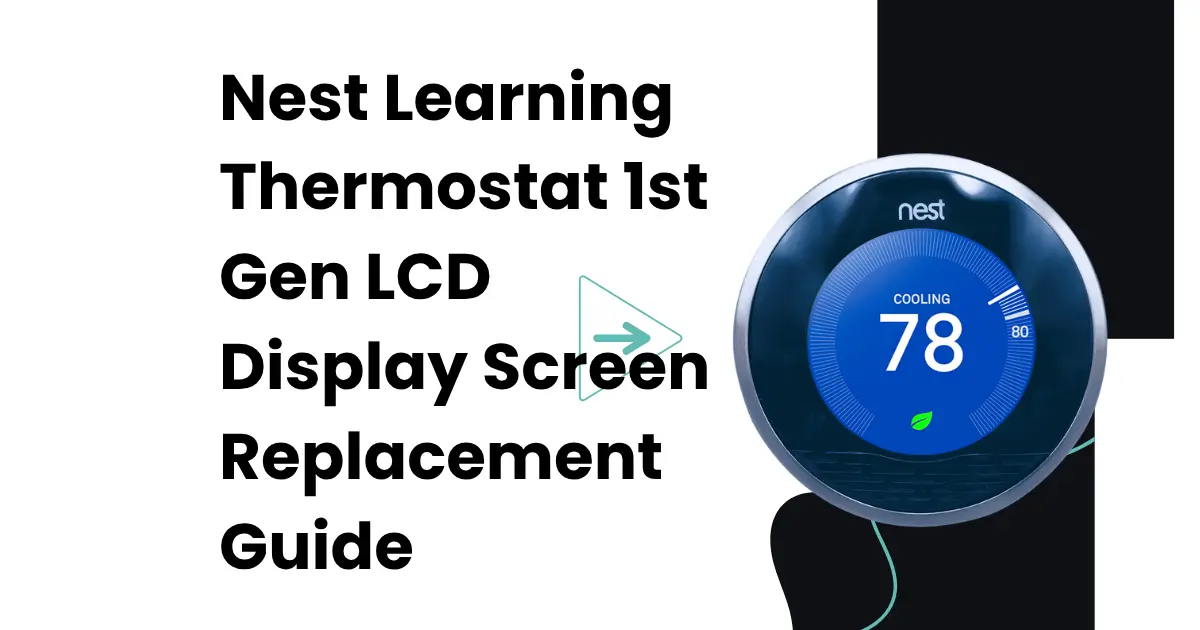
The LCD on the Nest Learning Thermostat 1st Generation is not merely a readout; it is the device’s entire visual identity and the surface through which every interaction with the thermostat’s learning algorithm, schedule, and HVAC status is communicated. It is a color, backlit, high-resolution circular display that was uncommonly sophisticated for a thermostat at the time of its 2011 release, and it remains the component that most defines the Nest 1st Gen’s distinctive character. When the display fails, whether through physical crack damage, delamination of the screen layers, backlight failure, or digitizer fault, the device becomes functionally inoperable despite having a fully functional logic board, battery, and HVAC control circuit beneath it.
Display replacement is the most technically demanding repair performed on the Nest 1st Gen; it requires precise handling of fragile ribbon cables, adhesive management, and careful reassembly of a circular display geometry that differs substantially from the rectangular screen replacements most electronics repair technicians encounter. This guide provides the complete procedure.
UNDERSTANDING THE NEST 1ST GEN DISPLAY ASSEMBLY ARCHITECTURE
The “display” in common usage refers to multiple stacked components that must be understood individually before any replacement attempt:
The LCD panel
The liquid crystal display matrix that produces the visual image: a circular, approximately 2.5-inch (320×320 pixel) IPS or similar technology panel. This is the component that cracks under physical impact or develops dead pixels or bleed zones.
The backlight
The LED-based illumination layer behind the LCD panel. Backlight failure produces a dark screen where the display content is still faintly visible under bright ambient light, a distinct symptom from complete LCD failure.
The digitizer/touch layer:
The Nest 1st Gen’s display surface does not use a conventional smartphone-style capacitive touch digitizer for input; primary input is through the rotating ring. However, the display face does detect the ring-press gesture through the display assembly’s mechanical travel. The front glass layer over the display is not a touch panel in the conventional sense.
The front glass/bezel
The protective glass panel over the LCD, bonded with optical adhesive or mechanical retention. Physical cracks in this layer alone (without LCD damage) require glass replacement rather than full LCD replacement.
These components are assembled as a single bonded unit in the Nest 1st Gen; they are not independently separable under field service conditions. Replacement is performed at the full display assembly level: the entire front glass + LCD + backlight unit is replaced as one piece.
DIAGNOSING WHICH DISPLAY COMPONENT HAS FAILED
Before sourcing a replacement, confirm the specific failure mode; different failure modes point to different components and different repair scopes:
Cracked screen with visible fracture lines: Physical LCD crack; full display assembly replacement required.
Screen is fully dark, no image visible even under bright light: Either LCD failure or complete backlight failure. Shine a bright flashlight at an angle against the screen surface in a dark room; if a faint image is visible, the LCD is functional, and backlight LED failure is the cause. If no image is visible even under a flashlight, the LCD panel itself has failed, or the display ribbon cable has been damaged.
Screen has image but severe bleed, discoloration, or black cloud in a corner: Delamination of display layers, typically caused by impact or excessive heat. Full display assembly replacement required.
Screen is dark, and device appears off, but battery and wiring are confirmed functional: This symptom display dark despite confirmed power is not necessarily a display failure. Before replacing the display, confirm battery voltage via the Nest Technical Info menu (if accessible through ring interaction in the dark) and attempt USB charging. A Nest that is powered but showing a blank screen due to battery voltage collapse does not have a failed display; it has a failed battery. The correct diagnostic path is covered in the companion guide Why Your Nest 1st Gen Screen is Blank and Won’t Turn On (Battery Death Fix).
TOOLS AND MATERIALS REQUIRED
- Plastic pry tools/spudgers (3-4, various widths; no metal pry tools)
- Precision Phillips screwdriver set (PH00 and PH000)
- Tweezers (plastic-tipped for ribbon cable handling)
- Heat gun or hairdryer (for adhesive softening during glass removal)
- Isopropyl alcohol (90%+) and cotton swabs
- Optical adhesive (UV-cure OCA film or liquid optical adhesive, if rebonding glass to LCD)
- Replacement display assembly (confirmed compatible with Nest 1st Gen, model T100577)
- Anti-static wrist strap
- Magnifying glass or loupe
- Clean work surface with good overhead lighting
SOURCING A COMPATIBLE REPLACEMENT DISPLAY
The Nest 1st Gen display is a proprietary circular display not used in any other consumer electronics device. Replacement displays are available from:
1. Third-party Nest repair parts suppliers (iFixit, eBay, specialized thermostat repair shops)
2. Harvested from non-functional Nest 1st Gen units with intact displays
When sourcing, confirm
- Compatibility specifically with “Nest Learning Thermostat 1st Generation / Model T100577” not Nest 2nd Gen or 3rd Gen (different display sizes and connector types)
- The ribbon cable connector type matches the logic board ZIF header
- The display has been tested before sale, if possible (some suppliers test and certify displays from donor units)
Avoid listings that describe “compatible with Nest” without specifying which generation; the display assemblies are not interchangeable between generations.
DISASSEMBLY SEQUENCE FOR DISPLAY ACCESS
Step 1 – Remove the display unit from the backplate
Pull the circular display head forward from the wall-mounted backplate. The magnetic retention releases with moderate force.
Step 2 – Remove the rotating stainless steel ring
The ring must be removed before the display assembly can be accessed. The ring retention and removal procedure is detailed in Nest 1st Gen Rotating Ring Assembly: How the Stainless Steel Mechanism Works. Apply outward lateral pressure at the bottom release point, then work around the circumference to release all retention clips.
Step 3 – Soften the display bezel adhesive
The front glass bezel of the Nest 1st Gen is bonded to the housing with adhesive around its circular perimeter. Apply gentle heat from a heat gun or hairdryer (set to low) to the front face for 30–45 seconds, keeping the heat source moving to avoid thermal concentration. The adhesive softens at approximately 60–70°C not hot to the point of burning, but warm enough that you can barely hold your finger on the surface.
Step 4 – Insert pry tools at the display edge
Working from the bottom edge of the circular display, insert a plastic pry tool into the gap between the glass bezel and the housing rim. Apply gentle lifting pressure to begin separating the adhesive bond. Work methodically around the circumference in small increments; do not lever at a single point, as this concentrates stress at that location and can crack the glass.
Step 5 – Locate and protect the ribbon cable
As the display assembly lifts free, a ribbon cable exits from the bottom edge of the display and routes to the logic board. This cable is the most vulnerable component in the entire repair it is thin, has a fixed length, and can be torn if the display is lifted too quickly or rotated in a direction that puts the cable under tension. As the display lifts, maintain awareness of the cable’s exit direction at all times.
Step 6 – Disconnect the ribbon cable at the logic board ZIF connector
Before lifting the display free, locate the ZIF (Zero Insertion Force) connector on the logic board where the ribbon cable terminates. Use a plastic pry tool or thumbnail to flip the ZIF lock upward (it pivots at the far end from the cable, lifting the clamping bar). Once unlocked, the ribbon cable slides out of the connector without force. Never pull the cable while the ZIF lock is closed.
Step 7 – Remove the display assembly
With the ribbon cable disconnected, the display assembly can be lifted completely free from the housing.
INSTALLING THE REPLACEMENT DISPLAY
Step 1 – Clean the housing recess
Remove all remnants of the old adhesive from the housing recess using isopropyl alcohol and a plastic scraper. The housing surface must be clean, dry, and free of adhesive residue for the new display to bond correctly.
Step 2 – Connect the replacement display ribbon cable to the ZIF connector
Before positioning the display in the housing, connect its ribbon cable to the logic board ZIF connector first. Slide the cable into the connector until it is fully seated (the insertion stop is felt as a subtle resistance). Flip the ZIF lock down to clamp the cable. Gently tug the cable; it should not pull free.
Step 3 – Test the display before final bonding
With the ribbon cable connected and the display held in position (not yet bonded), restore power by reattaching the display unit to the backplate momentarily. Confirm the display illuminates and shows the Nest interface. Test the rotating ring (reinstall it temporarily) to confirm the display responds correctly to input. Confirm all pixels are active and the image is uniform across the full display area. Only proceed to bonding after confirming functional operation.
Step 4 – Apply adhesive and bond the display
If the replacement display has a pre-applied adhesive ring (most replacement assemblies include this), peel the adhesive liner and position the display in the housing recess. Press firmly and evenly around the full circular perimeter for 30 seconds. If using liquid optical adhesive, apply per the adhesive manufacturer’s instructions.
Reinstall the rotating ring and reattach the display unit to the backplate.
POST-REPLACEMENT BEHAVIOR
After display replacement on the Nest 1st Gen, the device will typically boot normally and restore its previous settings from the device’s local storage. No reconfiguration of HVAC settings or schedule is required. The proximity sensor and activity sensor, which are separate from the display assembly, should function normally without recalibration.
If the display illuminates but shows incorrect colors, partial images, or display artifacts, the ribbon cable connection may be partially inserted in the ZIF connector. Power down, carefully reseat the ribbon cable, and re-test before concluding the replacement display is faulty.