The Central Control Unit in the Whirlpool GHW9100LQ is the electronic brain of the entire washer system. It receives input from every sensor and user interface component, executes the wash cycle logic, and sends control signals to every output device: the water inlet valves, the door lock, the drain pump, and the Motor Control Unit. When the CCU fails, the entire machine becomes non-functional regardless of whether all other components are working correctly. When the CCU sends or receives an incorrect signal, the machine misdiagnoses conditions and generates fault codes that mislead technicians into replacing functional components. Understanding the CCU’s architecture, its input/output functions, and its failure modes is the technical foundation for accurate diagnosis of every GHW9100LQ electronic fault.
CCU IDENTIFICATION AND PART NUMBERS
- Primary part number: WP8182706 (current Whirlpool service replacement)
- Superseded/cross-reference part numbers: 8182706, AP3866842, PS991618
- Compatible models (OEM cross-reference): GHW9100LQ, GHW9100LW, GHW9150PW, GHW9200LQ, GHW9200LW, and related Duet first-generation models
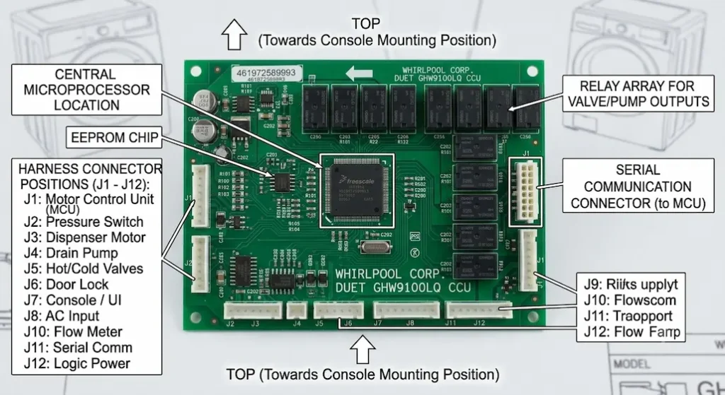
The CCU is located inside the machine’s top-front control panel housing, accessible after removing the top panel and the front control console. It is mounted horizontally, secured by screws to the console frame, with multiple wiring harness connectors on its rear and side edges.
Physical description
The CCU is a green or blue multi-layer PCB approximately 8 × 5 inches (20 × 12.7 cm), enclosed in a plastic housing on most service variants. The board contains a central microprocessor (the main logic IC), EEPROM memory for cycle data and fault logging, power supply circuitry for internal voltage regulation, relay drivers for high-current outputs, and opto-isolated inputs for sensor signals.
CCU INPUT SIGNALS: WHAT THE BOARD MONITORS
The CCU continuously monitors the following inputs to determine machine state and cycle progress:
User interface inputs:
- Cycle selector rotary switch position (which cycle is selected)
- Option button states (soil level, spin speed, temperature, extra rinse, delay)
- Start/Pause button state
- Control Lock (child lock) button state
Sensor inputs:
- Water level pressure switch signal (analog or frequency-based signal from the pressure transducer indicating drum water level)
- Door lock status signal (confirming door is locked before spin commences)
- Thermistor input (water temperature monitoring for accurate temperature-controlled wash)
- Lid/door switch redundancy input
Communication inputs:
- Serial communication bus from Motor Control Unit (MCU); the MCU reports motor speed, current draw, fault conditions, and confirmation of control signal receipt back to the CCU
The serial communication link between the CCU and MCU is the source of the F11 fault code (Serial Communication Error), one of the most common reported faults on this platform. When this communication link fails, the CCU loses all motor status information and cannot safely continue a cycle. The diagnostic and repair procedure for F11 is covered in the companion guide Troubleshooting Whirlpool GHW9100LQ Error Code F11 (Serial Communication Error).
CCU OUTPUT SIGNALS: WHAT THE BOARD CONTROLS
The CCU controls the following outputs through relay contacts and transistor drivers:
Valve outputs:
- Hot water inlet valve solenoid (opens to admit hot water)
- Cold water inlet valve solenoid (opens to admit cold water)
- Dispenser valve solenoid (routes water through the detergent/softener dispenser)
Electromechanical outputs
- Door lock solenoid (energizes to lock, holds locked during cycle, releases at cycle end)
- Drain pump motor (energizes to run the drain pump)
Communication outputs
- Serial command bus to MCU (sends speed commands, direction commands, and protection threshold parameters to the motor control board)
Display outputs:
- 7-segment or dot-matrix display for cycle status and fault codes
- Indicator LEDs for cycle stage, options selected, and child lock status
CCU POWER SUPPLY ARCHITECTURE
The CCU derives its operating power from the 120V AC mains supply, which it internally regulates to the low-voltage DC levels needed by its logic circuitry:
120V AC input → internal transformer or switching supply → 12V DC (for relay coils) → 5V DC (for microprocessor and logic ICs) → 3.3V DC (for memory and communication ICs, on some board variants)
Power supply failure on the CCU manifests as
- Complete control panel unresponsiveness (no display, no button response)
- Partial display activity (some LEDs light, others do not) indicates partial power rail failure
- Erratic behavior unrelated to cycle state indicates unstable regulated voltage
Electrolytic capacitor failure on the CCU power supply is a documented failure mode on boards of this era. Boards that have developed intermittent display or erratic behavior after many years of service often benefit from capacitor replacement on the power supply section, a repair that requires SMD soldering capability and is significantly cheaper than full board replacement.
CCU FAULT CODE GENERATION AND LOGGING
The CCU generates fault codes when sensor readings, communication responses, or component behaviors fall outside programmed tolerance ranges. Fault codes are displayed on the digital display and are simultaneously logged to the EEPROM memory; they persist after power cycles and can be retrieved in diagnostic mode.
Key fault codes originating from CCU processing
F01: EEPROM communication failure – the microprocessor cannot read/write to the EEPROM memory chip. Indicates CCU board failure.
F06: Motor control fault (CCU side) – the CCU is not receiving valid responses from the MCU.
F11: Serial communication error – loss of communication on the serial bus between CCU and MCU.
F14: EEPROM error – similar to F01; corrupted or inaccessible EEPROM data.
Fault codes related to components the CCU monitors (but originating from those components):
F02: Long drain – drain pump or drain path fault, reported to CCU by timeout of drain cycle
F20 / FH: Water inlet fault – CCU monitoring water level with no increase during fill
The procedure for entering diagnostic mode to read stored fault codes, including the button sequence on the GHW9100LQ, is covered in the companion guide How to Enter Diagnostic Test Mode on a Whirlpool Duet GHW9100LQ Washer.
CCU FAILURE MODES AND DIAGNOSIS
Symptom 1 – Machine is completely unresponsive (no display, no response):
Could be CCU power supply failure or main power supply fault (upstream of CCU). Confirm 120V AC is reaching the CCU’s power input connector before concluding CCU failure.
Symptom 2 – F11 fault code repeatedly:
The serial communication fault between CCU and MCU. The CCU itself may be functional; the F11 code indicates a communication problem that can originate from either the CCU serial output, the harness between boards, or the MCU serial input. Diagnosis involves isolating which board has the fault.
Symptom 3 – Erratic cycle behavior (wrong valves opening, cycles not progressing correctly):
Could be corrupted EEPROM on the CCU or relay driver failure allowing unintended relay states. Factory reset of the control board may resolve EEPROM corruption. The factory reset procedure is covered in How to Perform a Hard Factory Reset on Whirlpool Duet GHW9100LQ Control Board.
Symptom 4 – F01 or F14 fault codes:
Direct EEPROM failure indicates the CCU board has an internal memory failure and requires replacement.
REPLACEMENT AND SOURCING
Original Whirlpool service replacement CCUs (WP8182706) are available through Whirlpool parts distributors, online appliance parts retailers (RepairClinic, AppliancePartsPros, etc.), and used unit harvesting from donor GHW9100LQ machines.
Remanufactured CCU option: Several specialized appliance board repair services offer remanufactured GHW9100LQ CCU boards; these are original boards that have been repaired, recapped (electrolytic capacitors replaced), and tested. Remanufactured boards are typically less expensive than new OEM boards and often more reliable (the failure-prone electrolytic capacitors are proactively replaced)