The LED touch display board on the Levoit Core 200S is the physical interface between the user and every function the machine offers: power control, fan speed selection, mode switching, child lock, and the visual output of the air quality indicator ring. It is a compact multi-function PCB that integrates capacitive touch sensing, RGB LED driving, and communication with the main MCU in a single assembly. When it fails, or more precisely, when any of its subsystems fail, the symptoms can range from a single unresponsive button to a completely dark and non-interactive front panel, and the diagnostic challenge is isolating which subsystem within the board has actually failed.
This guide provides the schematic-level understanding of the display board, the diagnostic sequence for each failure mode, and the complete replacement procedure for when repair at the component level is not practical.
WHAT THE DISPLAY BOARD CONTAINS: A FUNCTIONAL SCHEMATIC
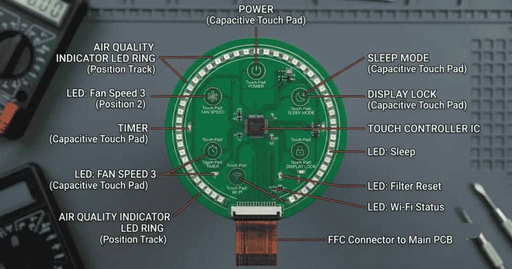
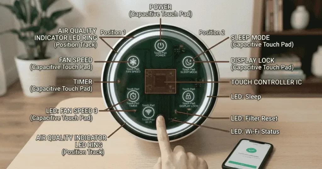
The Core 200S display board is a single-sided or double-sided PCB, typically 30–50mm in its longest dimension, mounted inside the upper housing with the touch surface facing the front of the unit. It contains the following functional circuits:
1. Capacitive touch sensor IC
The touch input functions (power button, fan speed/mode selection, lock button) are implemented using a capacitive touch sensing IC rather than mechanical switches. A capacitive touch sensor detects the change in electrical capacitance that occurs when a human finger approaches the electrode beneath the touch surface. The electrodes are conductive pads or traces on the PCB, positioned directly behind the outer housing surface that the user touches.
Common capacitive touch controller ICs in this product class: TTP223, TTP226, or equivalent single/multi-channel capacitive touch ICs. These ICs have very simple interfaces, a digital output that goes high or low when touch is detected, and are connected to the main MCU via GPIO lines.
2. Air quality indicator LED ring
The three-color air quality indicator (Blue/Orange/Red) is implemented with RGB LEDs, either discrete RGB LED components (red, green, and blue die in one package) or separate colored LEDs arranged around the indicator ring. The LED driving circuit consists of current-limiting resistors and, on some production variants, a dedicated LED driver IC for the ring configuration.
The color mapping:
- Blue: All sensors reading low particle density → green + blue channels active (or a single blue LED depending on variant)
- Orange: Moderate particle density → red + green channels active (producing orange/amber)
- Red: High particle density → red channel only active
3. Additional indicator LEDs
Separate from the air quality ring, the board hosts smaller indicator LEDs for:
- Power/standby state
- Filter replacement reminder
- Wi-Fi connection status
- Child lock indicator (on some variants)
4. Communication interface to main MCU
The display board connects to the main PCB via a flat flexible cable (FFC) or a multi-wire harness connector. This connection carries: power supply to the board, touch event signals from the touch IC to the main MCU, and LED control signals from the main MCU to the LED driver circuits.
HOW CAPACITIVE TOUCH WORKS ON THE CORE 200S
Understanding the capacitive touch mechanism is essential for diagnosing touch failures, because the technology is sensitive to conditions that mechanical switches are immune to.
The capacitive touch IC continuously monitors the capacitance of each electrode, the conductive pad behind the touch surface. Under no-touch conditions, the electrode’s capacitance is at a baseline determined by the PCB geometry and the dielectric properties of the housing material between the electrode and the outer surface. When a finger approaches, the human body adds capacitance to the electrode (the finger/body combination acts as a grounded conductor that couples capacitively with the electrode). The touch IC detects this capacitance increase and registers a touch event.
Sensitivity thresholds:
The touch IC typically has factory-configured sensitivity thresholds, the capacitance change required to register a touch. Sensitivity affects:
- How light a touch registers (too high sensitivity → false triggers from nearby objects or humidity; too low sensitivity → touch not registered unless pressed firmly)
- Proximity sensitivity (whether a near approach without contact triggers the sensor)
- Environmental factors that affect capacitive touch behavior
- Moisture on the touch surface: water on the housing surface adds capacitance to the electrode, potentially triggering false touches or preventing genuine touch registration (the IC interprets the wet surface as a permanent “touch”)
- Liquid ingress to the board: if moisture reaches the PCB surface near the touch electrodes, it can permanently shift the baseline capacitance, causing the IC to misinterpret all readings
- Metallic objects near the touch surface: placing a metal object (coin, tool) on or near the touch surface adds external capacitance and can trigger false touch events
- Child lock engagement: the child lock function is a firmware feature, not a hardware one. All touch inputs are disabled in the firmware while the child lock is active, regardless of the board’s physical function
DISPLAY BOARD FAILURE MODES AND DIAGNOSTIC SEQUENCE
Failure Mode 1:
All touch functions are unresponsive, LEDs are lit normally
Symptom: The air quality indicator ring and other LEDs illuminate correctly (the main MCU and power supply are functional), but no touch input produces any response.
Most likely cause: Touch controller IC failure, or the FFC/harness connection between the display board and main PCB has become partially disconnected (most common cause, especially in units that have been moved or had the housing partially disassembled).
Diagnostic: Power off, unplug, access the display board’s connector to the main PCB, disconnect and reconnect it firmly. Power on and test. If the issue persists after the connector reseating, the touch IC has failed.
Failure Mode 2
All touch functions unresponsive, all LEDs dark
Symptom: No LED illumination and no touch response.
Most likely cause: Power supply fault to the display board the FFC is disconnected, the display board’s power rail has no voltage, or the main PCB is not supplying power to the board.
Diagnostic: Confirm the main PCB is receiving power (the motor should respond if the unit is powered). If the motor runs but the display is completely dark, the power supply to the display board is interrupted.
Failure Mode 3
Single touch function unresponsive, others normal
Symptom: One specific button (e.g., the Lock button or the fan speed button) does not register touch, while others function normally.
Most likely cause: The specific touch electrode for that function has a failed trace, a contamination issue specific to that electrode area, or the touch IC’s channel for that electrode has failed.
Diagnostic: Clean the housing surface above the unresponsive electrode with isopropyl alcohol (remove any moisture or contamination). Test again. If the issue persists, the touch IC channel has failed, and display board replacement is needed.
Failure Mode 4
False touch events or phantom presses
Symptom: The unit changes modes, speeds, or activates/deactivates without being touched.
Most likely cause: Moisture on the housing surface or PCB, an external conductive object near the touch surface, or touch IC sensitivity calibration drift.
Diagnostic: Dry the exterior housing surface thoroughly. Remove any objects placed on or near the unit. If the phantom presses persist in a dry, clear environment, moisture has reached the PCB display board replacement is needed.
Failure Mode 5
The air quality indicator ring incorrect color or not functioning
Symptom: The air quality ring shows wrong colors or does not illuminate, while other functions work normally.
Most likely cause: RGB LED failure (one LED in the ring has burned out, changing the color mix) or LED driver circuit failure.
Diagnostic: This failure is typically cosmetic; the sensor and Auto mode still function correctly even if the LED ring misrepresents the reading. Display board replacement addresses this.
DISPLAY BOARD REPLACEMENT: STEP-BY-STEP PROCEDURE
When diagnostics confirm display board failure, either touch IC failure, persistent moisture damage, or LED driver failure, replacement is the practical repair path. Component-level repair (replacing individual ICs or LEDs) requires SMD soldering capability; board-level replacement is accessible to anyone comfortable with basic disassembly.
Sourcing the replacement board
The Core 200S display board is not listed as a standalone Levoit service part. Sourcing options:
1. Contact Levoit support with the unit’s serial number and request the display board part. Levoit may offer it as an out-of-warranty service part
2. Source from third-party electronics repair suppliers who stock common air purifier component boards
3. Purchase a second-hand Core 200S unit in working condition and harvest its display board
Confirm the replacement board matches the production variant of the failing unit. Display board configurations changed between production runs of the Core 200S, and the connector type and LED configuration may differ.
Disassembly to access the display board:
Step 1: Power off and unplug completely.
Step 2: Separate the base from the upper housing (counterclockwise 30-degree rotation and lift). Remove the filter assembly. Set the base assembly aside.
Step 3: On the upper housing, locate the screws securing the inner chassis to the outer shell. These are typically 2 to 4 Phillips-head screws accessible from the interior bottom rim of the upper housing. Remove them.
Step 4: The outer cylindrical shell of the upper housing typically separates from the inner chassis by unclipping from plastic retention clips around the perimeter. Apply gentle, even outward pressure around the seam while pulling the shell upward. Do not force the clips to release sequentially, not simultaneously.
Step 5: With the outer shell removed, the display board is visible on the inner chassis, positioned against the front face of the housing with its FFC or harness connector routed to the main PCB.
Step 6: Disconnect the FFC connector: if it uses a ZIF (zero insertion force) lock, flip the lock tab upward before pulling the cable. If it is a friction-fit harness, pull the connector straight out of its socket.
Step 7: The display board is typically secured by 1 to 2 screws or by the FFC connector tension alone. Remove any screws and lift the board free.
Step 8: Install the replacement board in the reverse sequence. Seat the FFC connector fully and engage the lock tab. Confirm the board is positioned correctly (touch electrodes facing outward) before reassembling the shell.
Step 9: Partial reassembly test: Before clipping the outer shell back in place, power on the unit and test all touch functions and LED indicators. Confirm correct operation, then complete reassembly.
CHILD LOCK AND TOUCH PANEL: A COMMON CONFUSION
The child lock function is a firmware-level touch disable implemented in the main MCU; it is not a hardware function of the display board. When child lock is active, the display board is functioning normally and sending touch events to the main MCU; the MCU is simply ignoring them. This means a display board that is “completely unresponsive” should always be tested with the child lock disabled before diagnosis proceeds. Child lock is deactivated by long-pressing the Lock button for 3 seconds. If child lock deactivation is not possible because all touch inputs are unresponsive, the issue is hardware (as described in the failure modes above) and not child lock.