The Arlo Q’s adjustable magnetic base is simultaneously one of its most practical features and one of its most misunderstood ones. The mounting system allows the Arlo Q to be placed on any ferromagnetic surface without tools, oriented in nearly any direction within a generous articulation range, and repositioned within seconds without leaving marks or requiring new hardware. Yet the same magnet-and-ball-joint design that makes this flexibility possible imposes specific constraints on where and how the camera can be reliably deployed, constraints that, when ignored, result in cameras that slip from position during operation, cables that pull the camera off its mount, or installations that fail in humid environments.
This guide covers every component of the Arlo Q mounting system the magnet assembly, the mounting plate, the ball-joint articulation mechanism, and the cable routing integration, with the technical depth needed to install it correctly and to choose the right mounting approach for each use case.
THE MAGNETIC BASE ASSEMBLY: COMPONENTS AND FUNCTION
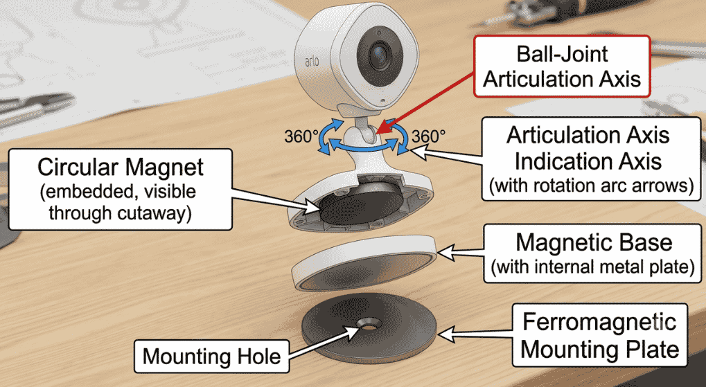
The Arlo Q’s base assembly consists of two primary components: the magnetic disc embedded in the camera’s base and the ferromagnetic mounting plate that the camera attaches to.
The camera-side magnetic disc:
A neodymium (NdFeB) permanent magnet is embedded in the flat circular base of the Arlo Q camera housing. Neodymium magnets are selected for their exceptional strength-to-size ratio. A neodymium magnet the size of a coin generates far more holding force than an equivalent ferrite magnet, allowing a thin camera base to generate meaningful mounting force.
The magnet is encased in the camera’s plastic base housing rather than exposed, which prevents direct contact corrosion and provides a smooth, non-scratching contact surface against the mounting plate.
The mounting plate:
The included mounting plate is a circular metal disc with a flat ferromagnetic surface on one side and a threaded mounting hole or adhesive backing system on the other side. The ferromagnetic surface is what the camera’s magnet adheres to.
The mounting plate can be:
- Screwed directly to a wall, shelf, or ceiling using the provided screws
- Adhered to a surface using double-sided adhesive tape (included in some package variants)
- Placed on an existing ferromagnetic surface (the camera can attach directly to a metal filing cabinet, refrigerator, or metal mounting bracket without the plate)
THE BALL-JOINT ARTICULATION MECHANISM
The Arlo Q’s camera orientation is adjustable through a ball-joint (ball-and-socket) mechanism integrated between the mounting plate and the camera body. The camera housing contains a ball joint that allows the camera to be tilted and rotated in any direction within its articulation range:
Pan (left-right rotation): approximately 180 degrees
Tilt (up-down angle): approximately 90 degrees
Combined articulation: the ball-joint design allows any combination of pan and tilt simultaneously, providing hemispherical coverage direction for camera pointing
The ball joint’s friction is calibrated to be stiff enough to hold the camera’s position against the gravitational load of the camera body (including the cable tension from the Micro-USB cable), but light enough to be repositioned by hand without tools. This friction is not adjustable; it is a fixed design parameter.
Two practical consequences of this friction calibration:
1. The cable creates a constant force on the camera that can displace the ball joint over time. A heavy, stiff cable (like a 15-foot 22 AWG cable) exerts more torque on the ball joint than the included 6-foot cable. For long cable installations, cable routing that minimizes the lever arm at the camera connection reduces the risk of gradual drift.
2. In environments with vibration (near HVAC vents, on surfaces adjacent to washing machines, near heavy foot traffic), the ball joint can incrementally drift over weeks of cumulative vibration exposure. Periodic verification and correction of the camera angle is appropriate in high-vibration environments.
MAGNETIC HOLDING FORCE AND WEIGHT CAPACITY
The magnetic connection between the Arlo Q and its mounting plate must hold the camera’s weight plus resist any forces applied by the cable. The Arlo Q weighs approximately 213 grams (7.5 oz), a modest load for a neodymium magnet of the type used in the base.
The direct ferromagnetic attraction force of the magnetic base, measured perpendicular to the plate surface (pure pull-off direction), is estimated at approximately 1.5–3 kg (3–6 lbs) based on the magnet’s physical dimensions and neodymium grade.
However, the relevant failure mode in mounted camera operation is not vertical pull-off but rather lateral sliding, the camera being displaced along the plate surface by cable tension or vibration. The lateral resistance (sliding force) of a magnetic connection is typically 40–60% of the perpendicular pull-off force. For the Arlo Q, this means lateral resistance of approximately 0.7–1.5 kg.
A heavy, gravity-hanging Micro-USB cable can exert 100–300 grams of lateral force on the camera base depending on cable weight, length, and routing angle. This force is within the magnetic connection’s lateral resistance capacity the camera will not typically slide, but in installations where the cable hangs freely rather than being routed along the wall, the cumulative cable tension and vibration can cause gradual position drift.
MOUNTING SURFACE COMPATIBILITY
Ferromagnetic surfaces (iron, steel, most stainless steel): The camera attaches directly without the mounting plate. This is useful for placing the Arlo Q on metal shelving, filing cabinets, or steel door frames without any installation.
Non-ferromagnetic surfaces (wood, drywall, plastic, aluminum, glass): The mounting plate must be installed first. Screw the mounting plate to the surface using the provided hardware, then attach the camera to the plate.
Ceiling installation
The magnetic holding force is adequate for ceiling installation with the provided mounting plate screwed to a ceiling joist or drywall anchor. The ball-joint articulation allows the camera to be angled downward from a ceiling position. For ceiling installations, verify that the mounting plate is secured to solid material (joist or stud) rather than drywall alone the vibration from an HVAC blower or foot traffic on the floor above can cause a drywall-only anchor to work loose.
Curved surfaces
The mounting plate is flat. On curved surfaces (rounded columns, curved cabinetry), the plate does not sit flush, creating a rocking contact that reduces the effective screw fastening area. On curved surfaces, use a flat piece of backing material between the curved surface and the mounting plate.
CABLE ROUTING INTEGRATION WITH THE BASE DESIGN
The Arlo Q’s Micro-USB cable enters the camera body at a port on the base the same section that contacts the mounting plate. On the camera base, a small channel or notch is provided to route the cable away from the magnetic contact surface, preventing the cable from being pinched between the camera base and the mounting plate.
Correct cable routing
The cable should exit through the designated channel and route away from the camera along the mounting surface rather than hanging freely below the camera. When the cable is routed along the wall to the mounting plate’s vicinity and then secured at intervals with cable clips, the mechanical load on the Micro-USB port and the ball joint is minimized.
Incorrect cable routing (hanging free)
If the cable exits the camera and hangs freely in the air, the cable’s weight creates a bending moment at the Micro-USB port that, over time, stresses the port’s internal PCB solder connections. For the Arlo Q’s power reliability, internal USB port integrity is critical. A damaged USB port’s symptoms include intermittent power loss and the complete failure-to-power-on scenario described in the companion guide Why is My Arlo Q Not Turning On? (Dead AC Adapter vs. Damaged USB Port Fixes).
MOUNTING PLATE INSTALLATION: SCREW SPECIFICATIONS
The mounting plate provided with the Arlo Q accepts the following fasteners:
For wood/wood stud: #8 × 1-inch wood screws (typically included)
For drywall with anchor: #8 × 1.5-inch screws with appropriate plastic wall anchors
For masonry/concrete: #10 masonry screws with pre-drilled holes
The mounting plate has a single central screw hole and, on some variants, two offset holes for greater stability. Using both holes (where available) doubles the fastening points and significantly improves resistance to vibration-induced loosening.
OUTDOOR USE LIMITATIONS
The Arlo Q is rated for indoor use only; it is not weatherproof and has no IP water resistance rating. The mounting system shares this limitation: the mounting plate’s steel construction will corrode in outdoor humidity conditions, and the neodymium magnet’s surface coating (typically nickel plating) degrades in outdoor environments. Additionally, temperature extremes outside the Arlo Q’s operating range (0°C to 40°C) can affect the magnet’s performance (extreme cold slightly reduces magnetic force in neodymium materials; extreme heat above 80°C causes permanent demagnetization, though this is far above normal operating temperatures).