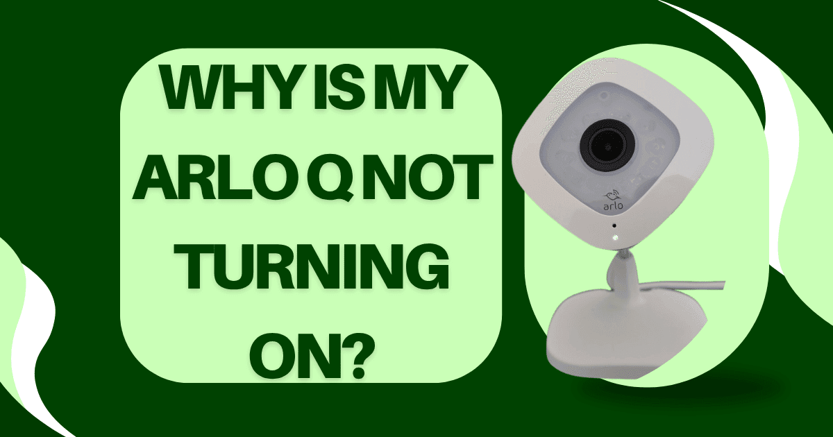
An Arlo Q that produces no response when connected to power no LED activity, no startup sound, no visible sign of life is presenting one of two fundamentally different failure conditions: either the power is not reaching the camera at all (an external power delivery problem), or the power is reaching the camera but the internal hardware cannot process it (an internal component failure). These two conditions look identical from the outside but require completely different repair approaches. Replacing the AC adapter when the actual fault is a damaged Micro-USB port, or attempting to clean the USB port when the fault is a failed AC adapter, wastes both time and money and leaves the camera non-functional.
This guide provides the complete diagnostic pathway for a non-powering Arlo Q structured as a series of isolation tests that progressively narrow the fault location until the specific failed component is confirmed.
UNDERSTANDING THE ARLO Q POWER CHAIN
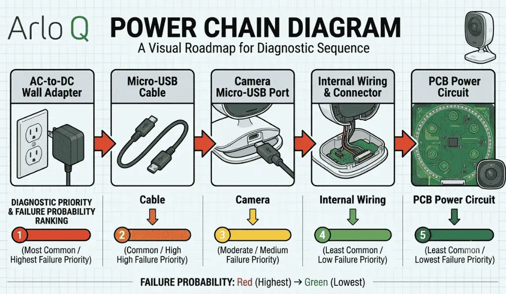
Before diagnosing, map the complete path that power must travel to reach the Arlo Q’s processor and LED:
Wall outlet → AC adapter (converts 120V AC to 5V DC) → Micro-USB cable (carries 5V DC) → Micro-USB port on camera (receives 5V DC) → power regulation circuit on main PCB → processor, LED, Wi-Fi chipset
A failure at any point in this chain produces the same observable symptom: no power, no LED, no response. The chain has five potential failure points, and the diagnostic sequence tests them in order from most common and cheapest to least common and most costly to address.
PRELIMINARY CHECK: CONFIRM THE WALL OUTLET IS FUNCTIONAL
Before examining the Arlo Q or its accessories, confirm the wall outlet is delivering power. Plug a known-functional device (a phone charger, a lamp) into the same outlet. If it works, the outlet is not the cause. If it does not work, check the circuit breaker or GFCI outlet reset.
This check takes ten seconds and eliminates the most trivially simple cause before proceeding.
DIAGNOSTIC TEST 1: ISOLATING THE AC ADAPTER
The Arlo Q’s included AC adapter is the single most common cause of no-power failure. The adapter is a compact switching power supply that contains a rectifier, a switching IC, and output filtering components, any of which can fail, particularly after years of continuous service or after a power surge event.
Adapter failure modes:
Complete output failure: The adapter produces no voltage at all. Most common cause: failed primary-side switching IC or open-circuit fuse inside the adapter.
Intermittent output: The adapter produces voltage at rest but sags or drops under load (when the Arlo Q starts to draw current). This produces a camera that flickers briefly during connection and then goes dark.
Overvoltage output failure: The adapter produces voltage above 5.5V, which triggers the camera’s over-voltage protection circuit and prevents operation. Less common but possible after a component failure in the adapter’s feedback circuit.
How to test the adapter (without a multimeter):
The simplest test is substitution: use a different USB charger capable of 5V/1A or higher output. Connect it to the Arlo Q’s Micro-USB port using the same cable. If the Arlo Q powers on, the original adapter has failed.
How to test the adapter (with a multimeter):
Set the multimeter to DC voltage measurement. Insert the Micro-USB cable into the adapter. Carefully probe the Micro-USB cable’s output end the outer contact of the Micro-USB connector is ground, and the inner contact (center pin) is the +5V output. Measure between them. A functional adapter at the 5V specification reads 4.75V to 5.25V at no load. Below 4.5V or above 5.5V indicates adapter failure.
The complete Arlo Q power specifications, including adapter output voltage and current requirements, are detailed in the companion guide Arlo Q Power Specifications: Voltage, Amperage, and AC Adapter Requirements.
DIAGNOSTIC TEST 2: ISOLATING THE MICRO-USB CABLE
If the adapter tests functional but the camera still does not power on, the cable is the next suspect. Cable failure modes include:
Open-circuit power conductor: The copper power conductor inside the cable has broken (typically at the cable end, where bending stress concentrates). The break may not be visible externally.
High-resistance power conductor: Partial wire fracture that allows current to flow at very low levels but creates a voltage drop sufficient to prevent the camera from receiving adequate power.
Corroded or damaged connector: The Micro-USB connector’s contact pins are bent, corroded, or contaminated, preventing adequate electrical contact with the port.
Cable test procedure:
Substitute a known-good Micro-USB cable of 24 AWG or better. Connect the confirmed-functional adapter to the substitute cable and connect to the Arlo Q. If the camera powers on, the original cable has failed.
DIAGNOSTIC TEST 3: ISOLATING THE ARLO Q’S MICRO-USB PORT
If both the adapter and cable test functional (substituting known-good components produces no change in behavior), the Arlo Q’s Micro-USB port is the next failure candidate.
The Micro-USB port on the Arlo Q is soldered directly to the main PCB. It is a mechanical component that sustains physical stress every time a cable is inserted or removed, and particularly when a cable is left connected, and the weight of the cable exerts a bending force on the port body.
USB port failure modes:
Broken solder joints: The five solder points that attach the port body to the PCB develop cracks from repeated flexing. The port may physically feel loose slight radial play when the cable is inserted, a subtle movement when the cable is wiggled. Broken solder joints can be reflowed by a technician with soldering capability.
Bent contact pins inside the port: If a cable was inserted at an angle or with force, one or more of the port’s internal contact pins can be bent out of alignment, preventing electrical contact with the cable’s corresponding contacts.
Port body mechanical failure: The port’s outer shell can delaminate from the contact carrier, causing the entire internal contact assembly to move as a unit when a cable is inserted rather than the cable’s pins making stable contact.
How to diagnose USB port damage:
Inspect the port opening visually with a bright flashlight and magnification. Look for:
- Any lateral movement of the port body when the cable is wiggled gently (indicates broken solder joints)
- Bent, pushed-back, or misaligned pins inside the port (indicates physical pin damage)
- Corrosion or debris in the port cavity (indicates contamination)
If pins are bent but not broken, careful repositioning with a fine non-metallic probe (toothpick) may restore contact. If pins are broken or the port is structurally compromised, port replacement requires PCB-level soldering.
DIAGNOSTIC TEST 4: FACTORY RESET ATTEMPT
Before concluding that an internal PCB failure is the cause (the most expensive and least common scenario), attempt a factory reset. The Arlo Q has a hardware reset button accessible on the device body; pressing it with a paperclip for 10+ seconds initiates a factory reset sequence that can clear firmware lock states that prevent normal startup.
In some cases, a firmware corruption event (from a power interruption during an update, for example) leaves the device in a non-responsive state that mimics hardware failure. The firmware state is non-responsive to all inputs, including the LED, making the device appear completely dead when it is actually in a firmware-level failure state rather than a hardware-level power failure.
After pressing the reset button:
If the LED activates during or after the reset press: The camera has power and is in a firmware/software failure state, not a hardware power failure. Factory reset will restore operation.
If the LED does not respond to the reset button press: Hardware power delivery failure is confirmed (adapter, cable, or port) or internal PCB failure.
DIAGNOSTIC TEST 5: INTERNAL POWER CIRCUIT FAILURE
If all external components (adapter, cable) have been confirmed functional with substitution tests and the USB port shows no physical damage, but the camera still produces no response, the internal power regulation circuit on the main PCB has failed.
Internal power circuit failures are uncommon and typically result from:
- Power surge damage (from a nearby lightning strike or a wiring event that sent a voltage spike through the outlet)
- Component aging failure in the power regulation IC (after many years of continuous operation)
- Liquid damage to the PCB (rare for an indoor camera but possible in high-humidity environments)
PCB-level power circuit repair requires SMD soldering expertise and is generally beyond home repair capability. At this diagnostic conclusion, the practical decision is between PCB repair by a specialist or replacement with a new or refurbished Arlo Q.
DECISION TREE SUMMARY
Outlet confirmed functional → substitute adapter → camera powers on: Replace original adapter.
Outlet and adapter confirmed functional → substitute cable → camera powers on: Replace original cable.
Adapter and cable confirmed functional → USB port has physical damage: Repair/replace USB port.
Adapter and cable confirmed functional → factory reset restores operation: Firmware corruption resolved.
All above confirmed functional, no response: Internal PCB power circuit failure; specialist repair or replacement.